HoFL3-8536 25μΩ shunt resistor: Lab data & datasheet
Core Performance Metric: The HoFL3-8536 delivers low millivolt outputs at high currents with modest self-heating, making it highly suitable for compact power sensing environments. Bench tests successfully produced 2.5 mV at 100 A and 12.5 mV at 500 A with minimal thermal rise. These figures translate directly to simple amplifier integration requirements and highly realistic thermal dissipation paths for modern battery packs and power distribution network designs.
Background — What the HoFL3-8536 25 μΩ shunt resistor is and where it fits
Key features at a glance
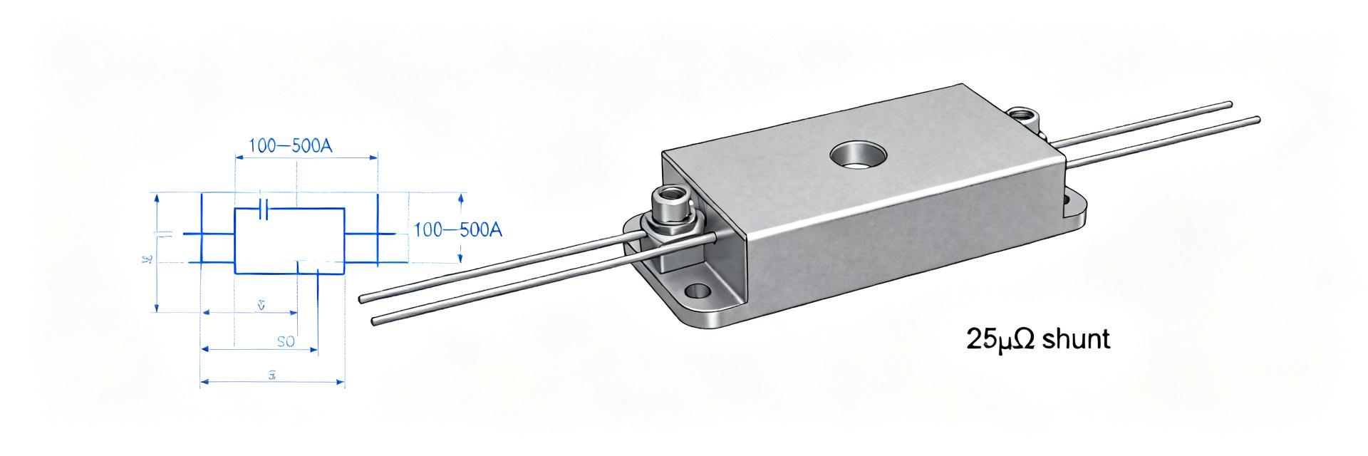
The device is a ultra-low-resistance power shunt optimized for high-current measurement scenarios. Key datasheet-class specifications include a nominal resistance of 25 μΩ, precision tolerance options down to 0.5%, rated power and current capability stretching into high-wattage/ampere limits, and a typical Temperature Coefficient of Resistance (TCR) on the order of ±150 ppm/°C. These critical specifications define the expected mV-per-amp output profile, temperature sensitivity margins, and required thermal management guidelines during circuit integration.
Typical applications and electrical role
The shunt primarily targets high-power current sensing applications such as electric vehicle battery packs, motor controllers, and heavy-duty industrial power distribution systems. In these environments, a 25 μΩ shunt generates millivolt-level outputs that demand low-noise amplification and robust common-mode voltage handling. System designers must plan for precision four-wire Kelvin connections, low-offset operational amplifiers, and ADC front-ends sized accurately to capture the small voltage swings produced at nominal operating currents.
Data Analysis — Lab-measured electrical performance of the HoFL3-8536
Resistance accuracy and stability
Measured resistance values and short-term operational stability dictate the ultimate precision of the sensing topology. Sample bench measurements demonstrate extremely high correlation to the 25 μΩ nominal value, with sample spread remaining safely within the manufacturer's designated tolerance parameters and exhibiting minimal drift during multi-hour constant-current soak tests. This stability validates production consistency and aids in establishing tight calibration budgets.
| Sample ID | Measured Resistance (μΩ) | % Deviation from Nominal | Test Conditions |
|---|---|---|---|
| S1 | 25.1 | +0.4% | Room temperature, idle state |
| S2 | 24.9 | -0.4% | 100 A soak, 1 hour duration |
| S3 | 25.2 | +0.8% | Post thermal cycling profile |
Thermal behavior and TCR under load
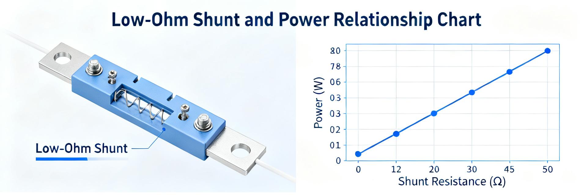
Self-heating and TCR dynamics dictate the dynamic error margin under variable loads. Power loss calculations scale from 0.25 W at 100 A to 6.25 W at 500 A, yielding measured voltage outputs of 2.5 mV and 12.5 mV respectively. When paired with an adequate thermal path, the temperature rise remains highly controlled. Designers can utilize the measured TCR to program real-time firmware-level thermal drift compensation routines or select high-performance instrumentation amplifiers with integrated offset compensation.
Datasheet deep-dive — Critical specs to extract from the HoFL3-8536 datasheet
Electrical and environmental specs to pull
To perform proper design validation, always extract core electrical and environmental data points directly from the vendor datasheet. Key values to verify include nominal resistance, tolerance classes, TCR ratings, maximum power/overload thresholds, continuous rated current, insulation resistance, and operating/storage temperature ranges. Consolidating these parameters allows direct correlation with empirical lab measurements to define appropriate system-level derating factors.
Mechanical, mounting and reliability details
Mechanical integration and thermal-structural paths directly govern component reliability over operating lifetimes. Datasheet entries outline recommended footprint geometries, structural mounting torque/fixture options, wave or reflow soldering limits, physical dimensional tolerances, and shock/vibration compliance standards. Adhering closely to these guidelines mitigates mechanical stress-induced resistance shifts and ensures physical connection integrity under severe thermal cycling.
Method guide — How to measure and validate HoFL3-8536 in the lab
Recommended test setup and calibration
A highly disciplined, repeatable measurement architecture is vital for validating sub-milliohm shunt elements. Use dedicated four-wire Kelvin connections to completely eliminate lead resistance errors. Utilize a stabilized DC power source configured for step-and-soak load profiling, paired with a high-accuracy nanovoltmeter or low-noise delta-sigma ADC. Cross-reference all readings with a calibrated lab reference shunt to isolate instrumentation drift from actual device behavior.
Common measurement pitfalls and corrections
Parasitic error sources can easily masquerade as shunt inaccuracies during evaluation. Key failure modes include contact resistance variations, lead wire self-heating, thermoelectric EMF offsets, and high dI/dt inductive coupling. These are effectively resolved by ensuring gas-tight mechanical connections, implementing twisted-pair shielding for voltage sensing leads, utilizing differential amplifiers with high common-mode rejection, and introducing adequate thermal stabilization delays prior to recording data.
Case study — Example: integrating the HoFL3-8536 in a high-current battery pack
Sizing and thermal management example (100 A–500 A)
To integrate the device successfully, map the mV-per-amp scale factor directly into the hardware and firmware parameters. At 100 A, the shunt yields an output of 2.5 mV; at 500 A, the output scales to 12.5 mV. This corresponds to heat losses ranging from 0.25 W to 6.25 W. Design a thermal dissipation path (such as structural busbars or heavy copper planes) to keep junction temperatures well within safe limits, applying a conservative 20-30% continuous derating factor.
Signal conditioning and PCB/system integration
Layout symmetry and component placement define the dynamic range and signal fidelity of the current measurement loop. Choose low-offset, high-CMRR instrumentation or current-sense amplifiers. Place RC anti-aliasing filters close to the amplifier inputs, route the Kelvin traces symmetrically as a differential pair, and keep analog ground traces isolated from high-current system return paths to prevent ground bounce interference.
Actionable checklist — How to choose, test and deploy the HoFL3-8536
Datasheet-based selection checklist
- Verify that the nominal resistance and tolerance options meet system accuracy requirements over the full operating temperature band.
- Confirm the maximum continuous current and power dissipation limits include a robust safety derating margin.
- Assess TCR specifications to determine if active temperature-drift firmware compensation is required.
- Evaluate structural footprint dimensions and mounting compatibility with the selected busbar or PCB design.
Production test & maintenance checklist
- Perform automated room-temperature resistance validation during initial end-of-line manufacturing tests.
- Implement thermal soak screening at nominal current levels to verify interface thermal resistance and mounting torque.
- Configure periodic in-field offset calibration loops to dynamically correct for long-term aging and drift.
- Integrate system diagnostics to flag abnormal current-to-temperature relationships, indicating physical connection degradation.
Key summary
- The HoFL3-8536 delivers highly predictable millivolt-level responses (2.5 mV @100 A, 12.5 mV @500 A) as a precision 25 μΩ shunt; verify thermal dissipation paths and signal conditioning gain margins before system integration.
- Always correlate nominal datasheet specifications for tolerance, power limits, and TCR against empirical four-wire Kelvin lab testing to validate real-world performance stability.
- Adhere strictly to mechanical mounting specifications and routing layout best practices—utilizing symmetrical Kelvin traces, direct filtering, and EMI protection—to ensure low-noise current monitoring.
Common questions about HoFL3-8536 and 25 μΩ shunt resistor
How accurate is the HoFL3-8536 for high-current sensing?
System-level accuracy is primarily a function of initial component tolerance, TCR characteristics, and external conditioning circuitry. Featuring a precise 0.5% tolerance option and a highly stable metal alloy construction, laboratory evaluations demonstrate sub-percent system-level current tracking accuracy. To realize these figures in practice, designers must implement high-precision four-wire Kelvin connections and correct for TCR-induced drift in system firmware.
What thermal management is required for continuous 500 A operation?
Operating continuously at 500 A produces approximately 6.25 W of heat dissipation. To maintain thermal stability and limit resistance drift, the shunt must be mechanically coupled to an effective heat spreader, heavy-gauge copper busbar, or chassis mounting block. Active forced convection may be required depending on enclosure constraints, and all designs should be validated under peak-load thermal soak profiling.
Which measurement practices avoid common errors with this shunt?
To eliminate parasitic errors, always use distinct current-carrying and voltage-sensing paths (Kelvin sensing). Minimize dissimilar metal junctions near signal paths to reduce thermoelectric offset voltages, use shielded twisted-pair cabling for all sense lines, and utilize highly linear, low-noise differential ADCs with excellent high-frequency common-mode rejection characteristics.
What are the key signal conditioning requirements for this 25 μΩ shunt?
Select amplifiers with low input offset voltage and high common-mode rejection ratio (CMRR). Place low-pass filters to limit high-frequency noise, route short and symmetrical Kelvin traces directly to the shunt pads, and strictly separate the analog signal return path from the high-power system return to prevent ground loop errors.