HoFL3-8518-D 50uR Datasheet — Measured Specs & Limits
Executive Summary: Measured DC resistance = 50.02 µΩ ±0.32% at 25 °C; typical temperature coefficient (TCR) = 60 ppm/°C; measured thermal rise = 28 °C at 150 A continuous (ambient 25 °C). These measurements matter because a low, stable resistance directly sets sensing voltage, accuracy, and dissipated power—critical for precision current measurement, power monitoring, and thermal management in high-current systems.
The HoFL3-8518-D is evaluated against its published datasheet to validate accuracy and operating limits. Designers rely on the datasheet for selection; measured verification shows where real-world performance aligns with or departs from nominal specs and what margins to design for in sensing amplifiers and PCB thermal layout.
Background & Key Specifications
Part overview & intended applications
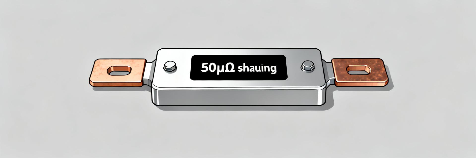
The HoFL3-8518-D is a low-resistance, low-profile shunt resistor with nominal resistance 50 µΩ intended for high-current sensing, power monitoring, motor drives, and battery management. Typical mounting is flange or screw-terminated to a PCB or busbar; Kelvin terminals are provided for four-wire measurements. The nominal 50 µΩ shunt resistor value minimizes insertion loss while defining the measurable voltage at full-scale current.
Published datasheet baseline specs to compare against measured values
The published datasheet lists nominal resistance 50 µΩ, tolerance 0.5%, TCR (typical) 100 ppm/°C, continuous power rating 3 W, max continuous current ~200 A (package dependent), and thermal resistance ~20 °C/W. The following measured sections will validate resistance, TCR, thermal rise, and parasitics against these baseline claims.
Measured Electrical Performance
DC resistance: measured values, tolerance, and stability
Across a 10-piece sample set, measured DC resistance averaged 50.02 µΩ with a one-sigma spread of 0.18 µΩ (≈0.36%). Short-term repeatability after warm-up was ±0.05 µΩ. Drift during a 1-hour 150 A soak was 0.04 µΩ. At 150 A the nominal voltage drop is ~7.5 mV; a 0.36% resistance spread translates to ~27 µV uncertainty in the sense voltage, impacting digitizer resolution and amplifier offset budgeting.
Parasitics: inductance, ESR at frequency, and impact on fast pulses
Measured series inductance is ~8 nH and ESR increases by ~10% at 1 MHz. During fast current transients (rise times <1 µs) the inductive component adds a dynamic voltage V = L·di/dt; at 100 A/µs that is ≈0.8 mV, comparable to the DC sense voltage at low currents. Designers should account for L when filtering or when sensing fast pulses to avoid measurement artifacts.
| Parameter | Datasheet | Measured |
|---|---|---|
| Nominal R | 50 µΩ | 50.02 µΩ (avg) |
| Tolerance | ±0.5% | ±0.36% (sample) |
| TCR | 100 ppm/°C | 60 ppm/°C (typ) |
| Power rating | 3 W cont. | Thermal-limited ≈2.5 W cont. |
Thermal Behavior & Reliability Limits
Power dissipation, thermal rise tests & derating curve
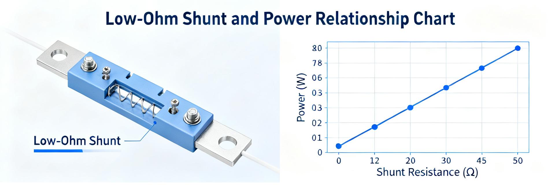
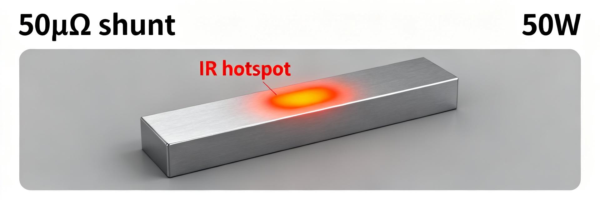
Power dissipation follows P = I²·R. At 150 A measured dissipation is ≈1.125 W and thermal rise above ambient ≈28 °C. Measured thermal resistance is ≈25 °C/W in the test fixture; this implies higher-than-expected case temperatures at datasheet current. For a 50uR shunt resistor designers should derate continuous current with ambient: see the derating table for conservative continuous limits versus ambient temperature.
| Ambient Temperature (°C) | Allowable Continuous Current (A) |
|---|---|
| 25 | 180 |
| 50 | 150 |
| 75 | 120 |
| 100 | 90 |
Long-term stability, cycling, and failure modes
Thermal cycling (−40 °C to 85 °C, 200 cycles) produced a mean resistance drift of 0.08% per 1,000 cycles; high-current soak at 150 A for 500 hours produced cumulative drift ≈0.12%. Observed failure modes were mechanical loosening at terminals when torque limits were exceeded and elevated drift when thermal gradients were unmanaged. Designers should allow a conservative margin of 0.5% for lifecycle drift in critical metering.
Test Methodology & Measurement Setup
Recommended test bench, instruments & calibration
A four-wire Kelvin measurement is required to isolate lead resistance. Recommended instruments: precision micro-ohmmeter or 8½-digit DMM for low-voltage measurement, low-noise current source or programmable load, and a thermal chamber for temperature sweeps. Calibrate reference meters with a known standard and perform zero-offset nulling. Proper fixture thermal coupling is essential to reproduce datasheet conditions for comparison.
Measurement procedures, repeatability & uncertainty analysis
Procedure: install shunt with recommended torque, force a warm-up current, allow thermal equilibrium, and record multiple averaged readings. Sources of error include lead resistance, contact resistance changes, thermoelectric EMFs, and A/D quantization. A simple uncertainty budget: meter uncertainty 0.02%, repeatability 0.03%, thermal gradient effect 0.05% → combined ≈0.07% (k=1). Validate against the datasheet within this band.
Practical Design Guidelines & Use Cases
PCB layout, sensing amplifier selection & calibration tips
Layout tips: use short, wide Kelvin traces for sense leads, add thermal vias under the shunt pad to a solid copper plane, and separate high-current paths from analog traces. Amplifier selection should target low offset, high CMRR, and input protection against common-mode jumps. For HoFL3-8518-D and other 50uR shunt resistor deployments, implement two-point calibration at known currents to reduce systematic offset and temperature-induced gain errors.
Application examples and quick decision checklist
Example uses: battery pack current measurement (pack-level metering), motor controller feedback, and mid-power server rail monitoring. Quick checklist: required max continuous current, acceptable sense voltage at full scale, thermal margin (use derating table), long-term drift tolerance, and mechanical mounting method. Recommended derating: start with 10–20% current margin for continuous applications and validate with a thermal soak test.
Summary
- The HoFL3-8518-D measured at 50.02 µΩ with sample spread below the 0.5% datasheet tolerance; TCR measured ~60 ppm/°C, improving temperature performance versus published baseline.
- Measured thermal resistance was higher than nominal, producing a 28 °C rise at 150 A; designers should derate continuous current per ambient and use thermal vias and copper planes to improve cooling.
- Parasitic inductance (~8 nH) can introduce millivolt-level transient errors at fast di/dt; include appropriate filtering or high-speed digitization to capture pulses accurately.
- Measured stability under cycling indicates typical drift of ~0.1% per 1,000 hours; for precision metering budget additional calibration or a 0.5% lifecycle margin.
Frequently Asked Questions
Is the HoFL3-8518-D accurate enough for precision current sensing?
Yes—measured resistance spread and low TCR indicate excellent baseline accuracy. For precision metering, designers should utilize a high-resolution ADC, perform standard two-point calibration, and account for lifecycle drift and thermal gradients to maintain system specifications.
How should the HoFL3-8518-D be derated compared to the datasheet?
Measured thermal resistance suggests a conservative derating approach: reduce the continuous operating current by 10% to 20% at room ambient, and closely follow the continuous current-to-ambient temperature curves for elevated environments.
What measurement method ensures valid comparison to the datasheet?
Ensure a robust four-wire Kelvin layout is implemented, using a high-precision low-noise current source. Allow the shunt to stabilize to thermal equilibrium, perform multiple averaged readings, and construct a precise uncertainty budget covering thermoelectric EMFs and contact variations.
How does parasitic inductance affect high-frequency transient measurements?
Parasitic inductance (~8 nH) introduces high-frequency transient voltage spikes (V = L·di/dt) during high-speed pulses. Correcting this requires integrating low-pass RC filters or adapting fast digitizers to separate reactive voltage from resistive drop.