TDP16031001BUF datasheet: key specs & performance brief
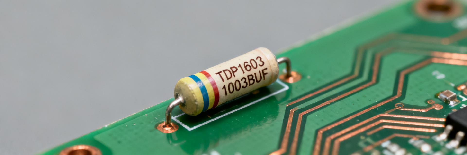
Quick reference: the TDP16031001BUF is a 16-pin thin-film resistor array offering 1 kΩ per element, ±0.1% tolerance, and a low temperature coefficient suitable for precision signal-chain applications. This brief walks through the datasheet highlights, expected electrical behavior, and practical design and test guidance for analog and digital designers, test engineers, and BOM buyers.
1 — Product overview & background
1.1 — What the part is and where it fits
Resistor arrays consolidate multiple precision resistors into a single package to simplify matching, pull-up networks, and termination. The TDP1603 resistor array family is targeted at ADC front-ends, precision instrumentation, and data-acquisition inputs where matched values and low drift reduce calibration burden and improve common-mode performance.
1.2 — Key identifiers to find in the datasheet
Scan the datasheet for full part number, per-element nominal value, tolerance code, package code, pinout diagram, and ordering variants. Add a quick checklist: part number, resistance per element, tolerance, TCR spec, power per element, maximum working voltage, and package outline reference.
2 — Key specs & electrical performance
2.1 — Electrical parameters to prioritize
Prioritize nominal resistance (1 kΩ), tolerance (±0.1%), TCR (ppm/°C), power rating per element, maximum working voltage, and noise specification. Extracting these clarifies accuracy, temperature drift, and allowable dissipation; for example, low TCR reduces ADC gain error over temperature and tight tolerance lowers initial calibration time.
| Key Parameter | Value / Spec | Engineering Significance |
|---|---|---|
| Nominal Resistance | 1 kΩ (per resistor) | Ideal impedance balance for high-speed op-amps and ADC inputs |
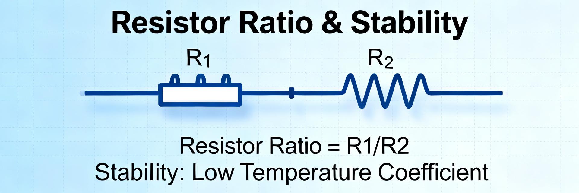
| Absolute Tolerance | ±0.1% | Reduces raw gain and ratio alignment error during initial build |
| Ratio Matching Tolerance | ±0.05% (typical) | Guarantees precise attenuation balance in differential configurations |
| TCR Tracking | ±5 ppm/°C | Maintains thermal tracking between relative internal channels |
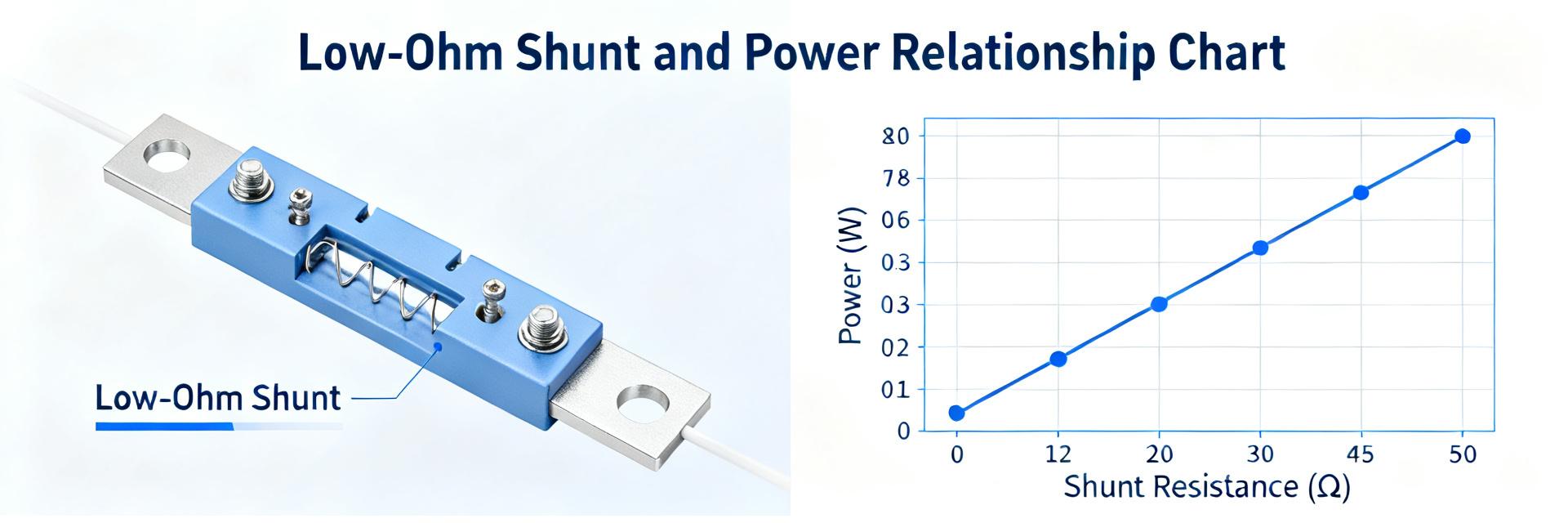
| Power Rating | 100 mW per element | Prevents local self-heating and resultant parameter drift |
2.2 — Typical test/characteristic curves to interpret
Focus on resistance vs. temperature, long-term stability (ppm/1000 h), power derating, and any frequency-response data. Summarize curves by noting expected drift across the recommended operating range and the derating behavior under elevated ambient or localized PCB heating.
3 — Package, pinout & layout guidance
3.1 — Mechanical & thermal considerations
Note package type, pin pitch, overall dimensions in mm and inches, soldering profile, and maximum junction/ambient temperatures. PCB layout should include correct pad geometry, controlled solder fillet, and thermal vias if arrays dissipate appreciable power or sit near heat sources.
3.2 — Pinout and routing best practices
Read the pinout diagram to identify element endpoints and common pins. Route matched pairs with equal trace lengths, use short Kelvin traces for critical sense paths, and apply ground guarding or ground floods between noisy digital traces to reduce crosstalk and common-mode injection.
4 — Applications, test setups & performance examples
Example 1: Precision Voltage Divider
A typical placement ahead of an ADC where matched 1 kΩ elements reduce ratio error and temperature drift. Thermal tracking ensures that even under rapid temperature shifts, the attenuation ratio remains structurally locked.
Example 2: Multichannel Bus Interface
Used as a multi-channel pull-up network for digital buses. This setup simplifies routing, guarantees consistent pull strengths, and secures identical rise times across parallel transmission paths.
4.2 — How to validate performance on the bench
Use a 4-wire ohm meter for resistance verification, perform thermal soak tests to estimate TCR, and run a low-noise amplifier chain to measure noise contribution. Pass/fail criteria: measured tolerance within specified limit, TCR within datasheet ppm/°C budget, and no unexpected power derating behavior under expected loading.
5 — Comparison & alternatives
5.1 — How to benchmark against similar resistor arrays
Compare tolerance, TCR (ppm/°C), long-term stability, available packages, and price-per-channel. Build a short weighted checklist: tolerance (40%), TCR (25%), stability (15%), package fit (10%), cost (10%) to quantify trade-offs when substituting parts.
5.2 — When to pick a different approach
Choose discrete resistors if per-channel thermal isolation or higher power is required, or pick higher-power arrays when dissipation per element exceeds package capability. Use tighter tolerance classes or matched-pair options when system-level calibration cost exceeds component cost savings.
6 — Design checklist & procurement/testing tips
6.1 — Pre-design checklist
- Confirm required tolerance and TCR align with overall system error budgets.
- Verify maximum voltage and continuous power per element don't exceed nominal values.
- Ensure physical footprint and package pitch are compatible with target manufacturing lines.
- Verify derating margins and thermal performance under worst-case ambient excursions.
6.2 — Procurement and lifecycle notes
Order characterization samples and perform lot-to-lot checks for resistance spread and TCR. For BOM control request documentation: date codes, test reports, and qualification data. Maintain alternative source strategies and plan acceptance tests for incoming lots.
Summary
- TDP16031001BUF Core Highlights: Integrates 1 kΩ elements with ±0.1% tolerance and low tracking TCR, making it suitable for precision ADC front-ends and matched-divider applications.
- Selection Parameters: Compare options along the axes of tolerance, TCR tracking, long-term stability, physical package scale, and individual thermal limits.
- Implementation Rules: Apply 4-wire resistance testing during verification, enforce symmetrical routing, and maintain short layout lines to preserve precision matching properties.
FAQ
What test methods confirm values in a TDP16031001BUF datasheet?
Use a calibrated 4-wire ohm meter for base resistance, apply controlled temperature steps to estimate TCR, and perform long-duration stability tests under representative bias to check drift. Confirm power derating by applying incremental dissipation while monitoring resistance change and thermal rise.
How does the TCR in the datasheet affect ADC accuracy with this resistor array?
TCR expressed in ppm/°C predicts resistance change per degree; multiply TCR by temperature swing to estimate gain or divider ratio error. Low TCR reduces temperature-induced gain error, lowering calibration frequency and improving long-term measurement stability in precision converters.
When is a discrete resistor preferred over a resistor array like this?
Choose discrete resistors when per-channel thermal isolation, higher individual power dissipation, or physically separate placement is necessary. Discretes are also preferable when custom tolerance or specialized packages are required for extreme-environment applications.
How does layout symmetry preserve the matching performance of the TDP16031001BUF?
Layout symmetry ensures both elements of a matched pair experience identical thermal gradients and parasitic capacitances. Routing paths should use equal trace widths and lengths, and be placed symmetrically relative to nearby heat sources on the PCB.