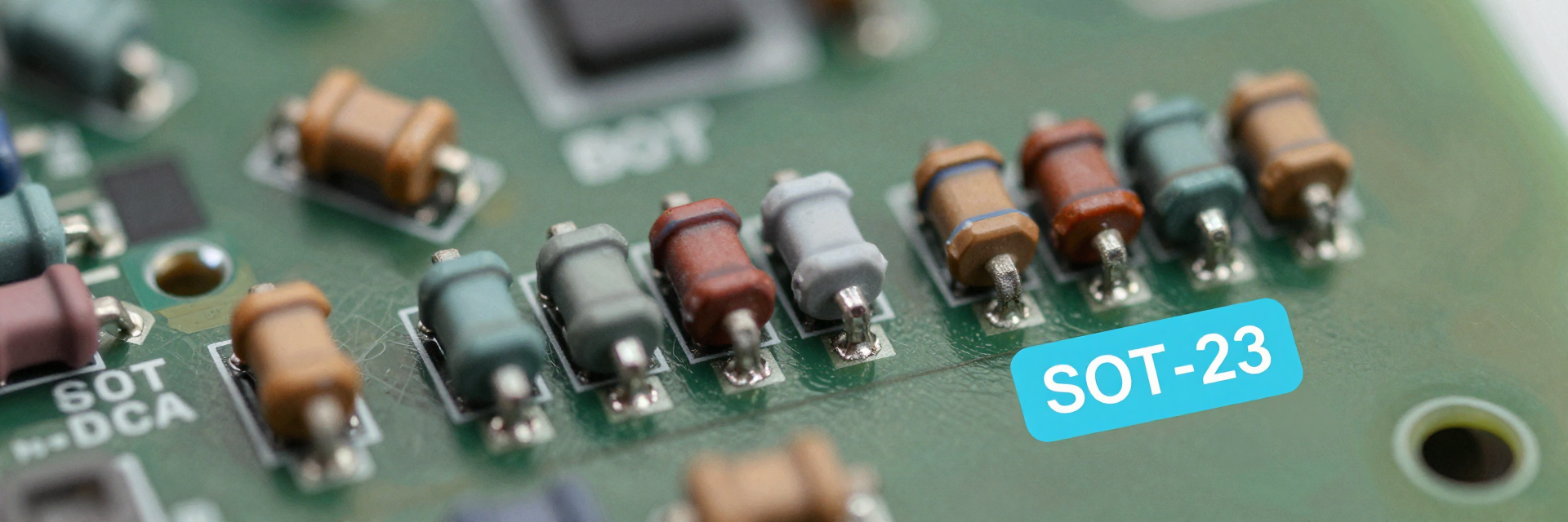
MPMT2002AT5 Specs: Why ±25ppm Tracking Matters for Precision Analog Circuits
In high-precision analog design, a 1% initial tolerance error is often acceptable, but thermal drift is the silent killer. Data shows that in instrumentation amplifiers and voltage dividers, mismatched temperature coefficients can introduce errors exceeding 500 ppm over a standard -40°C to +85°C operating range. This article dissects the MPMT2002AT5 resistor network specs, explaining why its ±25 ppm/°C tracking characteristic is not just a datasheet number, but a critical requirement for maintaining signal integrity in modern US-market precision circuits.
Decoding the MPMT2002AT5 Datasheet Metrics
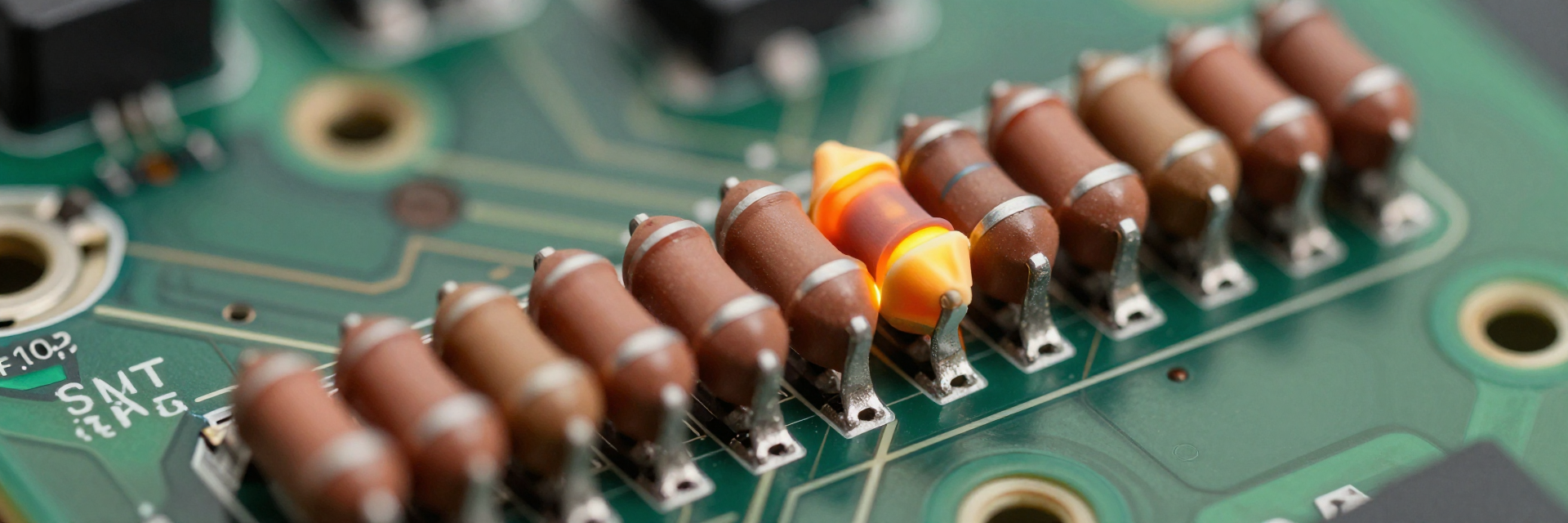
You must look beyond absolute resistance values when evaluating this component. The true value lies in how closely the internal resistors track each other as temperature fluctuates.
Initial Tolerance vs. Thermal Tracking
While initial tolerance defines the resistance at 25°C, thermal tracking defines stability across the operating range. For the MPMT2002AT5, the ratio tolerance remains tight even as individual resistances shift. You should prioritize matching characteristics over absolute accuracy because differential measurements rely on ratios, not single-point values. A ±0.1% initial tolerance paired with poor tracking will fail in dynamic environments, whereas tighter tracking ensures consistent performance regardless of ambient changes.
The Significance of ±25 ppm/°C Ratio Stability
The ±25 ppm/°C specification indicates how much the ratio between two resistors changes per degree Celsius. In practical terms, if you use this network in a gain-setting configuration, the gain error due to temperature is minimized significantly compared to discrete pairs. This level of stability is crucial for systems requiring calibration-free operation over wide temperature ranges, reducing long-term maintenance costs and ensuring regulatory compliance in medical or industrial applications.
Engineering Impact on Precision Analog Topologies
Understanding where these specs apply helps you justify component selection in your schematic reviews.
Voltage Divider Accuracy in ADC Front-Ends
In analog-to-digital converter (ADC) front-ends, voltage dividers scale input signals to match reference voltages. If the divider’s ratio drifts, the digital output code becomes inaccurate, introducing non-linearity. Using an MPMT2002AT5 ensures that the scaling factor remains constant despite thermal gradients on the PCB. This preserves the effective number of bits (ENOB) of your data acquisition system, preventing measurement errors that could compromise sensor data integrity.
Differential Signal Matching in Instrumentation Amps
Instrumentation amplifiers rely on matched resistor networks to reject common-mode noise. Mismatched tracking leads to degraded Common Mode Rejection Ratio (CMRR). By selecting components with ±25 ppm/°C tracking, you maintain high CMRR across temperature swings. This is vital in noisy industrial environments where differential signals are susceptible to interference. Consistent matching ensures that your amplifier rejects unwanted noise rather than amplifying it due to imbalance.
Comparative Analysis: Thin-Film Networks vs. Discrete Resistors
You might wonder why integrated networks are superior to pairing two high-quality discrete resistors. The answer lies in physical proximity and manufacturing consistency.
Parasitic Capacitance and Thermal Coupling Advantages
Discrete resistors suffer from varying thermal coupling; one may heat up faster than the other due to board layout or airflow. Integrated thin-film networks like the MPMT2002AT5 share a common substrate, ensuring both elements experience identical temperature changes simultaneously. This intrinsic thermal coupling eliminates differential drift caused by environmental asymmetry. Additionally, the compact SOT-23 package reduces parasitic capacitance, which is beneficial for high-frequency signal paths.
Cost-Benefit Breakdown for High-Volume Production
| Feature | Discrete Pair | MPMT2002AT5 Network |
|---|---|---|
| Assembly Time | Higher (two placements) | Lower (one placement) |
| Matching Quality | Dependent on lot selection | Factory calibrated tracking |
| Board Space | Larger footprint | Compact SOT-23 |
For high-volume production, the reduced assembly time and elimination of manual matching processes make the network more cost-effective overall, despite a slightly higher unit price. It also reduces inventory complexity by consolidating two parts into one SKU.
Implementation Best Practices for Design Engineers
To maximize the benefits of this component, follow specific layout and selection guidelines.
PCB Layout Strategies for Optimal Thermal Uniformity
Even with excellent internal tracking, external heat sources can affect performance. Place the MPMT2002AT5 away from power transistors or high-current traces. Use thermal relief pads on ground connections to prevent heat sinking away from the device unevenly. Symmetrical routing around the package ensures uniform temperature distribution, preserving the assumed ±25 ppm/°C tracking behavior in simulation models.
Selection Criteria: When to Upgrade from ±50 ppm to ±25 ppm
Upgrade to the ±25 ppm/°C variant when your system requires less than 100 ppm total gain error over the full temperature range. If your application operates in controlled environments with minimal thermal variation, ±50 ppm may suffice. However, for automotive, aerospace, or outdoor industrial sensors exposed to rapid temperature changes, the tighter tracking provides necessary margin against drift-induced inaccuracies, ensuring reliable long-term performance without frequent recalibration.
Key Takeaways
- The MPMT2002AT5 offers ±25 ppm/°C ratio tracking, essential for minimizing thermal drift in precision analog circuits.
- Integrated thin-film networks provide superior thermal coupling compared to discrete resistor pairs, ensuring stable performance across temperature ranges.
- Use these networks in ADC front-ends and instrumentation amplifiers to maintain high CMRR and accurate voltage division.
- For high-volume production, they reduce assembly time and inventory complexity while offering better reliability.
- Prioritize thermal tracking over initial tolerance when designing for wide operating temperature ranges.
Frequently Asked Questions
What does ±25 ppm/°C tracking mean for the MPMT2002AT5?
It means the ratio between the internal resistors changes by no more than 25 parts per million for every degree Celsius change in temperature. This ensures that gain or division factors remain stable despite thermal fluctuations, which is critical for precision analog circuit accuracy.
Why choose a resistor network over discrete resistors?
Resistor networks like the MPMT2002AT5 offer factory-matched tracking and shared thermal exposure. Discrete resistors may have similar initial tolerances but lack guaranteed ratio stability under temperature changes, leading to potential errors in differential measurements and voltage dividers.
How does temperature affect precision analog circuits using this part?
Temperature affects resistance values, but the key issue is mismatched drift. With ±25 ppm/°C tracking, both resistors drift together proportionally. This maintains the intended circuit function, such as gain or attenuation, preventing signal distortion or measurement errors in sensitive instrumentation setups.
When should I upgrade from ±50 ppm to ±25 ppm tracking?
Upgrade to the ±25 ppm/°C variant when your system requires less than 100 ppm total gain error over the full temperature range. For automotive, aerospace, or outdoor industrial sensors exposed to rapid temperature changes, tighter tracking provides necessary margin against drift-induced inaccuracies.