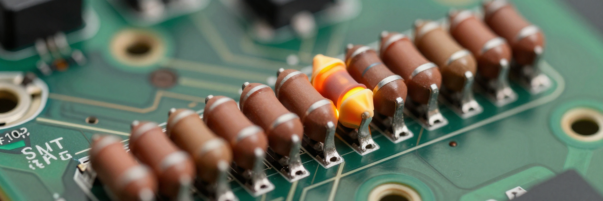
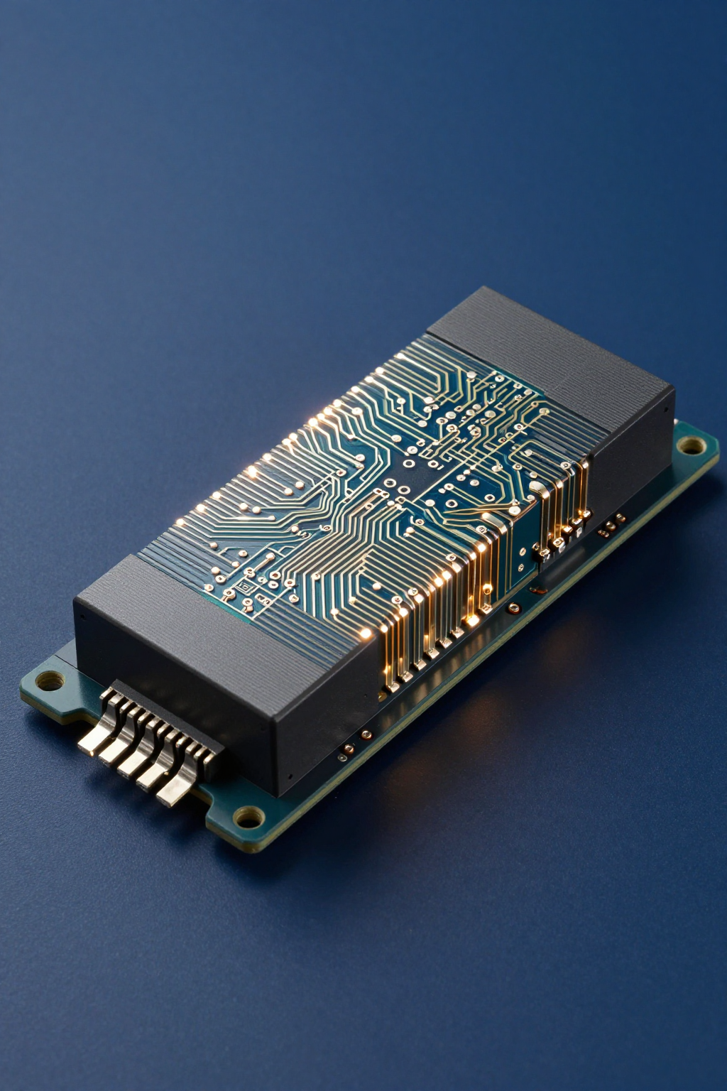
MPMT10019001AT5 Deep Dive: Specs, Tolerances & Performance Data
In high-precision analog front-end designs, the margin for error is measured in parts per million. The MPMT10019001AT5 thin-film resistor divider stands out not just for its compact SOT-23 footprint, but for delivering a ratio tolerance as tight as 0.01% and tracking stability of ±2 ppm/°C. But how do these specs translate to real-world circuit performance? This analysis breaks down the critical tolerances, thermal behavior, and application fit for this specific part number, providing engineers with the data needed to validate their next design iteration.
Decoding the Part Number & Core Specifications
Breakdown of the MPMT Series Nomenclature
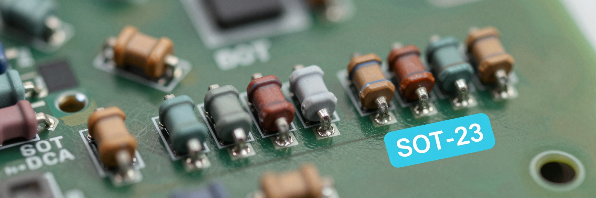
You should first understand the naming convention to ensure you are selecting the correct variant. The "MPMT" prefix identifies the series as a molded, surface-mount thin-film resistor network. The numeric string "10019001" encodes the resistance values; specifically, it denotes a 1 kΩ / 9 kΩ configuration. The suffix "AT5" indicates the package type (SOT-23) and the precision grade. Recognizing these codes prevents costly assembly errors during the prototyping phase.
| Parameter Segment | Code Value | Interpretation |
|---|---|---|
| Series Prefix | MPMT | Molded Precision Thin-Film Network |
| Resistance Values | 10019001 | R1 = 1kΩ, R2 = 9kΩ (1:9 Ratio) |
| Package/Precision | AT5 | SOT-23 Package, High Precision Grade |
Key Electrical Parameters: Resistance Values & Power Ratings
The core electrical specs define the operational boundaries. Each element within the divider has a nominal resistance value that must be matched against your voltage reference requirements. The total power rating for the package is typically limited by the thermal characteristics of the SOT-23 footprint, usually around 0.2W to 0.25W depending on ambient conditions. You must derate this power capacity if the device operates in elevated temperatures to prevent long-term drift or catastrophic failure.
Precision Analysis: Ratio Tolerance & Tracking Stability
Understanding the 0.01% Ratio Tolerance Impact
The defining feature of this component is its ultra-tight ratio tolerance. A 0.01% mismatch means the relationship between the two resistors remains constant regardless of absolute resistance shifts. In differential ADC applications, this directly impacts the Integral Non-Linearity (INL). If you use discrete resistors with standard 1% tolerances, the worst-case ratio error could exceed 2%, significantly degrading signal fidelity. The integrated tolerances here guarantee superior matching accuracy.
Thermal Tracking Performance Across Operating Temperatures
Temperature coefficients (TC) are often overlooked until field failures occur. The MPMT10019001AT5 exhibits a tracking TC of ±2 ppm/°C. This low value ensures that as the board heats up during operation, both resistors change resistance at nearly identical rates. Consequently, the division ratio remains stable. For US electronics manufacturing environments where ambient temperatures may fluctuate, this thermal stability is critical for maintaining calibration over the product's lifecycle.
Mechanical & Environmental Reliability Data
SOT-23 Package Dimensions and PCB Layout Considerations
The physical form factor influences both density and reliability. The SOT-23 package allows for high-density placement, which is essential for modern compact devices. However, you must account for parasitic capacitance and inductance introduced by the lead frames. Proper PCB layout involves minimizing trace lengths from the divider to the input pins of subsequent components. This reduces noise pickup and ensures that the theoretical specs are realized in practice.
Moisture Sensitivity Level (MSL) and Long-Term Drift Metrics
Reliability extends beyond initial testing. This component typically carries an MSL level suitable for standard reflow soldering processes, reducing the risk of "popcorn effect" during manufacturing. Long-term drift metrics indicate how the resistance values shift after thousands of hours of operation. High-quality thin-film technology minimizes this aging effect, ensuring that your design meets longevity requirements without frequent recalibration cycles.
Comparative Performance vs. Discrete Resistor Solutions
Matching Accuracy: Integrated Divider vs. Two Separate Components
When comparing integrated dividers to discrete solutions, the advantage lies in inherent matching. Two separate resistors, even if purchased from the same batch, will have independent temperature coefficients and absolute tolerances. The integrated structure shares a common substrate, ensuring that thermal gradients affect both elements equally. This results in a ratio error that is orders of magnitude lower than what is achievable with discrete pairs, enhancing overall system precision.
Board Space Savings and Assembly Cost Efficiency
While the unit cost of an integrated divider may appear higher than two discrete resistors, the total cost of ownership is often lower. You save significant board real estate, allowing for smaller form factors. Furthermore, assembly time is reduced because there is only one pick-and-place operation instead of two. This efficiency aligns with lean manufacturing principles prevalent in US production lines, optimizing both space and labor resources.
Target Applications & Design Integration Guidelines
Ideal Use Cases: ADC Reference Dividers and Sensor Signal Conditioning
This component excels in scenarios requiring precise voltage scaling. Common applications include dividing high-voltage rails down to safe levels for Analog-to-Digital Converters (ADCs) and conditioning signals from strain gauges or thermocouples. In these contexts, the tight tolerances ensure that the digital representation accurately reflects the physical measurement, preventing data integrity issues in industrial control systems.
Best Practices for Minimizing Noise and Crosstalk in Layout
To maximize performance, adhere to strict layout guidelines. Place the divider close to the source and load to minimize loop area. Use ground planes effectively to shield sensitive traces from digital switching noise. Additionally, consider using Kelvin connections if measuring very low voltages. These practices help preserve the signal-to-noise ratio, ensuring that the high precision of the component is not compromised by external interference.
Key Takeaways
- The MPMT10019001AT5 offers 0.01% ratio tolerance, significantly outperforming discrete resistor pairs in matching accuracy.
- With a tracking TC of ±2 ppm/°C, it provides exceptional thermal stability for high-precision analog circuits.
- The SOT-23 package saves board space and reduces assembly costs compared to using multiple discrete components.
- Ideal for ADC reference dividers and sensor conditioning where long-term reliability and low drift are critical.
Frequently Asked Questions
What does the 0.01% ratio tolerance mean for my circuit?
It means the relative difference between the two resistor values is extremely small. Even if absolute resistance changes due to temperature, the division ratio stays consistent. This is crucial for maintaining accuracy in voltage references and measurement systems, ensuring your output data remains reliable under varying conditions.
Can I replace discrete resistors with this integrated divider easily?
Yes, provided the pinout matches your existing design or you adjust the layout accordingly. The transition simplifies assembly and improves performance. However, verify that the power dissipation limits of the SOT-23 package meet your application's thermal requirements to avoid overheating issues during operation.
How does thermal tracking improve stability over time?
Thermal tracking ensures both resistors react similarly to temperature changes. Unlike discrete components with independent drifts, the integrated pair maintains its ratio. This reduces calibration needs over the product's lifespan, making it ideal for industrial applications where maintenance access is difficult or expensive.
Why choose an integrated divider over two separate resistors?
Integrated dividers share a common substrate, ensuring thermal gradients affect both elements equally. This results in significantly lower ratio errors compared to discrete pairs, even from the same batch. It also saves PCB space and reduces pick-and-place assembly steps, lowering total cost of ownership.