FF150R12W2T7EB11BPSA1 Datasheet: Key Specs & Pinout Guide
Struggling to decode the FF150R12W2T7EB11BPSA1 datasheet for your high-power inverter design? This 1200V, 150A IGBT module offers robust performance but requires precise integration. Here is how you can quickly master its key specifications and pinout configuration to ensure reliable operation.
Decoding the Part Number & Core Specifications
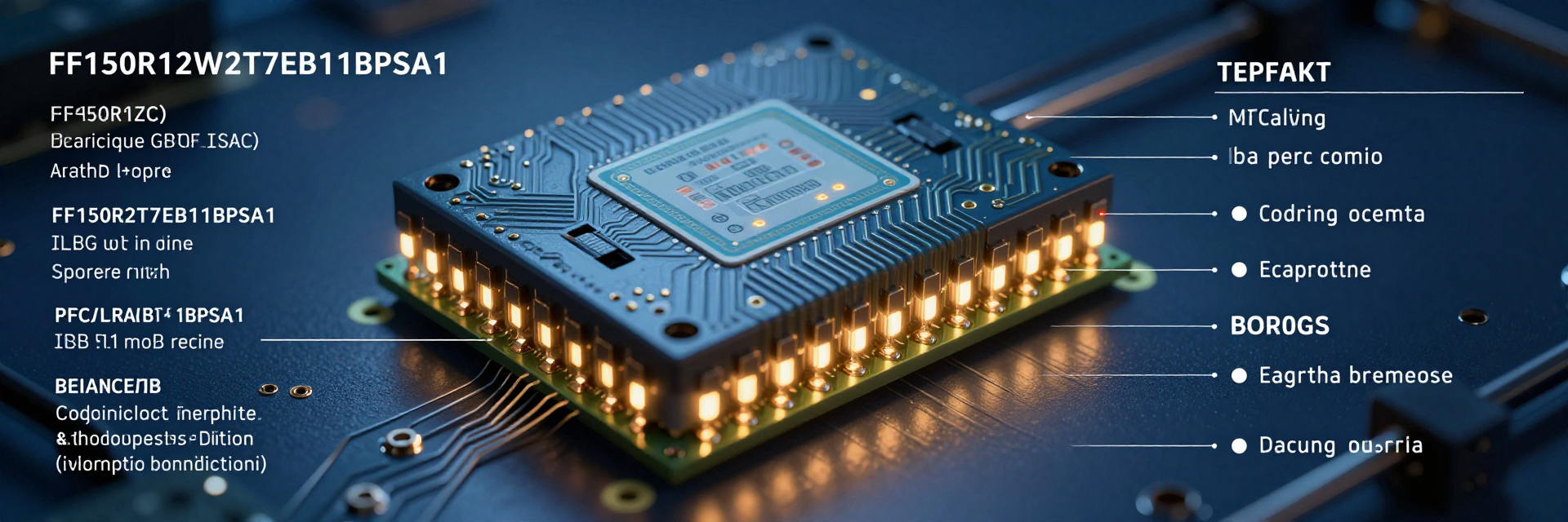
You need to understand the naming convention to select the right component. The prefix "FF" denotes a half-bridge module, while "150" indicates the nominal current rating of 150 Amperes. The "12" represents the collector-emitter voltage (VCES) class of 1200 Volts. The suffix "W2T7EB11BPSA1" specifies the package type, trench field-stop technology, and specific automotive or industrial qualification standards. Ignoring these details can lead to thermal runaway or voltage breakdown in critical power systems.
| Parameter | Symbol | Value | Unit |
|---|---|---|---|
| Collector-Emitter Voltage | VCES | 1200 | V |
| Nominal Collector Current | IC nom | 150 | A |
| Max Junction Temperature | Tj max | 175 | °C |
| Topology | - | Half-Bridge | - |
Understanding the FF150R12W2T7EB11BPSA1 Naming Convention
The part number structure is systematic. Each segment provides immediate insight into the device's capabilities. For instance, the "T7" generation signifies advanced trench gate technology, which reduces switching losses compared to older planar designs. You should verify that the package dimensions match your PCB footprint before ordering. Mismatched footprints cause assembly delays and potential short circuits during initial testing phases.
Critical Electrical Ratings: VCES, IC Nom, and Tj Max
The maximum junction temperature (Tj Max) is typically 175°C, allowing for significant thermal headroom. The nominal collector current (IC Nom) of 150A assumes ideal cooling conditions. In practical applications, derating curves must be consulted. If you operate near the limit without adequate heatsinking, the device will fail prematurely. Always cross-reference the safe operating area (SOA) charts provided in the technical documentation to ensure your load profile remains within safe boundaries.
Pinout Configuration & Internal Topology
Correct pinout identification is non-negotiable for circuit integrity. The FF150R12W2T7EB11BPSA1 features a standard half-bridge topology. You must distinguish between the DC link terminals and the AC output pins. Miswiring can result in catastrophic shorts across the DC bus. Use multimeter continuity checks on bare modules to verify internal connections before soldering them onto your board.
Half-Bridge Inverter Layout Explained
The internal schematic consists of two IGBTs and two freewheeling diodes arranged in a half-bridge. One switch connects to the positive DC rail, while the other connects to the negative rail. The midpoint serves as the phase output. This configuration is ideal for three-phase inverters when combined with two additional modules. Understanding this layout helps you design effective snubber circuits to manage voltage spikes during commutation events.
Gate Emitter vs. Collector Terminal Identification
Gate and emitter terminals are physically smaller than the main power terminals. You must maintain strict isolation between the control signal and the high-voltage power path. Creepage distances specified in the datasheet are critical for preventing arcing. Ensure your PCB layout respects these minimum distances. Using isolated gate drivers is highly recommended to protect your control logic from high-voltage transients present at the emitter terminal.
Thermal Management & NTC Thermistor Integration
Efficient heat dissipation extends the lifespan of the IGBT module. The built-in NTC thermistor allows for real-time monitoring. You should integrate this sensor into your control loop to adjust switching frequency dynamically based on temperature readings. Proper mounting torque ensures optimal contact resistance between the module baseplate and the heatsink.
Leveraging the Built-in NTC for Real-Time Temperature Monitoring
The NTC thermistor provides direct feedback on the chip temperature. Unlike external sensors, it measures the actual die temperature, which is the limiting factor for reliability. Calibrate your ADC inputs to match the NTC resistance curve. Implement software filters to smooth out noise. If the temperature exceeds predefined thresholds, reduce the duty cycle or shut down the system to prevent irreversible damage to the silicon.
Optimal Heatsink Selection and Mounting Torque Guidelines
Select a heatsink with low thermal resistance relative to the power loss generated. Apply thermal interface material evenly to eliminate air gaps. Tighten screws in a diagonal pattern to distribute pressure uniformly. Over-torquing can crack the ceramic substrate, while under-torquing increases thermal resistance. Consult the mechanical data sheet for specific Newton-meter values to ensure a secure and thermally efficient connection.
Design Considerations for High-Reliability Applications
High-reliability designs require meticulous attention to switching characteristics. Low saturation voltage (VCE,sat) reduces conduction losses. However, faster switching increases electromagnetic interference (EMI). Balance these factors by optimizing gate resistor values. Shielding and proper grounding techniques are essential to mitigate noise coupling into sensitive control circuits.
Mitigating Switching Losses with Low VCE,sat Characteristics
The trench field-stop technology minimizes VCE,sat, reducing heat generation during conduction. To further optimize efficiency, minimize the Miller plateau duration by adjusting gate drive strength. Excessive gate speed can cause ringing due to parasitic inductances. Add small ferrite beads or RC snubbers at the gate terminals if necessary. Monitor waveforms with an oscilloscope to ensure clean switching edges without overshoot.
Safe Operating Area (SOA) and Overload Protection Strategies
Operate strictly within the SOA limits defined in the datasheet. Short-circuit withstand time is limited; typical values range from 5 to 10 microseconds. Implement desaturation detection in your gate driver to identify faults quickly. Upon detecting a short circuit, immediately turn off the IGBT to prevent destruction. Redundant protection layers, such as fuses and current limiting resistors, add safety margins for unpredictable load conditions.
Common Troubleshooting & Application Pitfalls
Field failures often stem from installation errors rather than component defects. Common issues include poor thermal contact, incorrect gate drive voltages, and insufficient decoupling capacitors. Systematic troubleshooting involves checking each stage of the power chain. Document all parameters during commissioning to establish baseline performance metrics for future maintenance.
Diagnosing Early Failure Modes in Industrial Drives
Early failures usually manifest as increased leakage current or abnormal heating. Inspect the module for discoloration or bulging cases, which indicate internal stress. Measure the impedance between collector and emitter; infinite resistance is expected when off. A low reading suggests damaged semiconductor junctions. Replace the module immediately if any anomalies are detected to avoid cascading failures in the inverter bridge.
Best Practices for Gate Driver Circuit Matching
Ensure the gate driver output voltage matches the IGBT’s requirements, typically +15V for turn-on and -8V to -15V for turn-off. Negative bias prevents false triggering due to noise. Keep gate loops as short as possible to minimize inductance. Use twisted pair wires for gate and emitter signals. Verify that the driver’s peak current capability exceeds the IGBT’s input charge requirement to achieve fast switching times without strain.
Key Takeaways
- Master the FF150R12W2T7EB11BPSA1 datasheet by understanding its 1200V/150A ratings and trench field-stop technology benefits.
- Verify pinout configuration carefully to prevent shorts, ensuring proper isolation between gate/control and power terminals.
- Implement rigorous thermal management using the built-in NTC thermistor and correct mounting torque for optimal heat dissipation.
- Protect the module by adhering to Safe Operating Area (SOA) limits and utilizing desaturation detection for overload protection.
Frequently Asked Questions
What is the maximum junction temperature for the FF150R12W2T7EB11BPSA1?
The maximum junction temperature (Tj) is typically rated at 175°C. This high limit allows for greater thermal headroom in demanding industrial environments. However, continuous operation near this limit reduces lifespan. Engineers should aim to keep operating temperatures well below 150°C for long-term reliability, utilizing appropriate heatsinks and active cooling solutions to maintain optimal thermal conditions.
How do I interpret the pinout diagram in the datasheet?
The pinout diagram shows a half-bridge configuration with two IGBTs and two diodes. Identify the DC+ and DC- terminals for the power supply connection. The AC terminals connect to the motor or load. Gate and emitter pins are separate for each switch. Pay close attention to creepage distances between high-voltage and control pins to ensure electrical safety and compliance with regulatory standards.
Why is the NTC thermistor important in this IGBT module?
The NTC thermistor provides real-time temperature monitoring of the silicon chips. It enables dynamic adjustment of switching frequencies or shutdown protocols if overheating occurs. Without this feedback, the system cannot protect itself against thermal runaway. Integrating the NTC into your control loop enhances safety and prolongs the operational life of the FF150R12W2T7EB11BPSA1 module.
What are the critical electrical ratings for this module?
Key ratings include VCES (Collector-Emitter Voltage) of 1200V, IC Nom (Nominal Collector Current) of 150A, and Tj Max (Maximum Junction Temperature) of 175°C. Always consult derating curves for practical applications.