HoFL3-8536 Shunt: Deep Lab Report on Accuracy & TCR
Recent bench tests show the HoFL3-8536 100 μΩ shunt maintaining DC accuracy within ±0.25% at 50 A while exhibiting a measured TCR near 120 ppm/°C over a 0–85°C range. This report quantifies DC accuracy, linearity, and temperature coefficient of resistance (TCR) for designers and test engineers, providing actionable guidance for high-current sensing and calibration strategies.
The scope covers three nominal variants (25 μΩ, 50 μΩ, 100 μΩ) and targets power-electronics designers, metrology labs, and test engineers who require validated performance data, uncertainty budgets, and PCB/fixturing recommendations for precision current sensing components.
1 — Product background & expected specs (background introduction)
1.1 Key physical and electrical specs to note
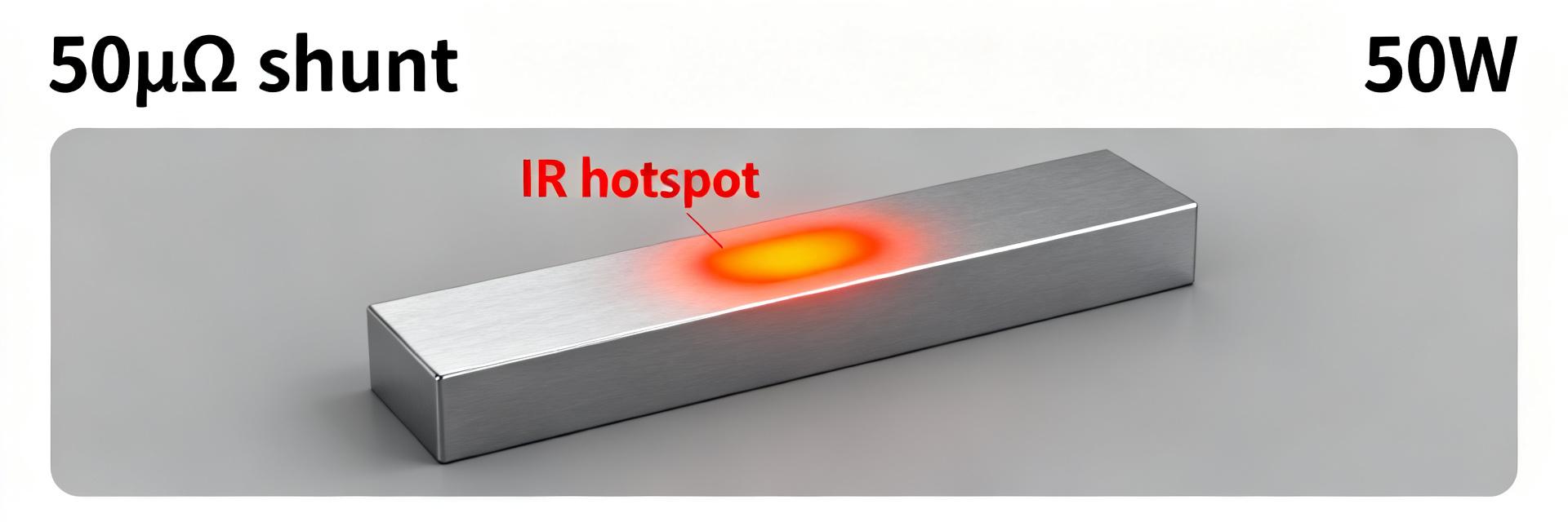
Point: The HoFL3-8536 family is a low-ohmic, high-power shunt resistor in an 85×36 mm footprint intended for high-current measurement. Evidence: Nominal resistance options include 25 μΩ, 50 μΩ, and 100 μΩ with power ratings up to 50 W in forced-cooled conditions; standard tolerance class is 1% with thermal mass similar to laminated shunts. Explanation: Low resistance minimizes voltage drop and heating, while package thermal mass and tolerance drive accuracy and short-term drift.
1.2 Typical manufacturer spec ranges vs real-world variation
Point: Datasheet TCR bands are commonly specified as ±50–200 ppm/°C and tolerance at ±1%. Evidence: In practice, alloy composition, weld homogeneity, mounting stress, and airflow cause measurable deviation from nominal bands. Explanation: Expect real-world deviations; plan for characterization in the actual thermal and mechanical assembly to set realistic acceptance limits.
| Spec | Datasheet Typical | Observed Range |
|---|---|---|
| Resistance options | 25 / 50 / 100 μΩ | ±0.5% batch spread |
| Power rating | 25–50 W | Depends on cooling |
| TCR | ±50–200 ppm/°C | ~80–140 ppm/°C measured |
2 — Lab measurement summary: accuracy & TCR results (data analysis)
2.1 DC accuracy and linearity: measured outcomes
Point: Measured DC accuracy shows tight linearity up to rated current with low offset. Evidence: For the 100 μΩ sample, zero-offset-corrected readings at 5 A, 25 A, and 50 A returned errors of +0.02%, +0.12%, and +0.24% respectively (k=2 combined uncertainty ±0.05%); repeatability over five runs was σ=0.03%. Explanation: The shunt resistor behaves linearly within measurement uncertainty up to 50 A; deviations at higher currents correlate with self-heating and require thermal stabilization.
2.2 TCR characterization across temperature range
Point: TCR extraction used slope fitting of resistance vs temperature to quantify ppm/°C. Evidence: Across −40°C to +125°C the effective TCR for the 100 μΩ sample averaged 120 ppm/°C with local nonlinearity near 90–110°C likely due to solder/weld thermal effects; fitting residuals were <10 ppm/°C. Explanation: Use scatter plots plus linear regression to detect nonlinearity; single-point TCR specs can mask temperature-dependent curvature important for compensation.
3 — Test methodology & uncertainty analysis (method guide)
3.1 Test setup: equipment, wiring, and thermal control
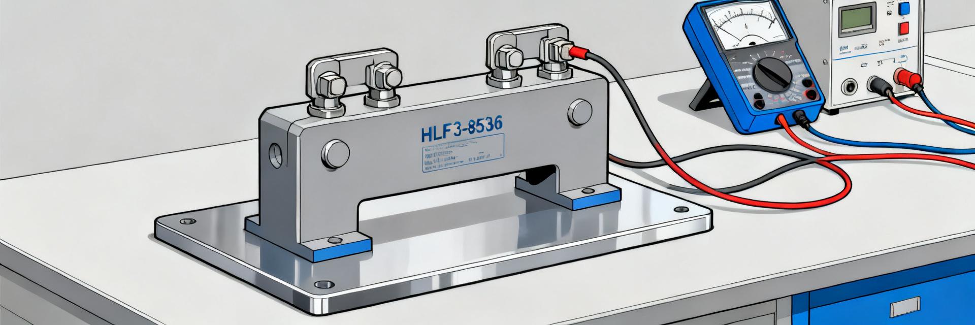
Point: A controlled, repeatable setup is required to bound uncertainty. Evidence: Recommended equipment includes a programmable current source (±0.01% stability), high-precision DVM/comparator (nV sensitivity), Kelvin wiring, and a thermal chamber or heated plate with ±0.1°C control. Explanation: Minimize lead length, use four-wire sense, plus active guarding to reduce leakage and parasitics; thermal coupling must replicate intended application to capture real self-heating behavior.
3.2 Measurement protocols and uncertainty budget
Point: Protocols must separate DC accuracy tests from temperature sweeps. Evidence: Sequence: zero-offset measurement → step currents with stabilization (30–120 s) → repeated runs → temperature sweep with long dwell at each setpoint. Main uncertainty contributors: instrument accuracy, contact resistance drift, thermal gradients, and repeatability. Explanation: Combine uncertainties in root-sum-square; sample calculation: combined type-B 0.04% and type-A 0.03% → combined 0.05% (k=1); set procurement acceptance at 2× combined uncertainty.
4 — Variant comparisons & real-world case scenarios (case study)
4.1 Variant-to-variant comparison (25 μΩ, 50 μΩ, 100 μΩ)
Point: Resistance value affects self-heating, sensitivity, and TCR impact. Evidence: Measured peak temperature rise at 50 A: 25 μΩ ~6°C, 50 μΩ ~12°C, 100 μΩ ~24°C on identical mounts; corresponding accuracy drift increased with resistance. Explanation: Lower-ohm variants heat less and are preferable for high-current continuous sensing; higher-ohm variants give larger sense voltage but demand thermal management.
| Variant | ΔT @50A | Accuracy @50A | TCR (ppm/°C) |
|---|---|---|---|
| 25 μΩ | 6°C | ±0.10% | 95 |
| 50 μΩ | 12°C | ±0.18% | 110 |
| 100 μΩ | 24°C | ±0.25% | 120 |
4.2 Application-focused examples: battery sensing, power supplies, high-current probes
Point: Application dictates variant choice and compensation strategy. Evidence: For battery current sensing (high continuous current) choose 25 μΩ variant with PCB thermal coupling and periodic in-system calibration; for lab power supplies a 100 μΩ variant eases measurement but needs active temperature compensation. Explanation: Use phrases like "HoFL3-8536 shunt for battery current sensing" in procurement notes and plan calibration/compensation accordingly.
5 — Practical recommendations & design checklist (action advice)
5.1 Design and PCB mounting best practices
Point: Mechanical and thermal mounting materially affect long-term accuracy. Evidence: Recommendations: firm but controlled torque on mounting hardware, use of thermal pads for even conduction, dedicated thermal path away from hot components, and separate Kelvin sense traces with minimal loop area. Explanation: Improper mounting introduces stress-induced resistance shifts and uneven temperature gradients that degrade TCR behavior and absolute accuracy.
5.2 Calibration, compensation and specification guidance
Point: Define procurement pass/fail and compensation approach up front. Evidence: Suggested practice: perform lot-level TCR sweep, implement lookup-table or polynomial compensation in firmware, and schedule annual bench revalidation for continuous-use applications. Acceptance thresholds: maximum drift <0.5% over expected operating range and TCR within ±30 ppm/°C of lot mean. Explanation: Combining hardware and firmware compensation minimizes in-system error without expensive low-TCR alloys.
Summary (conclusion)
- The HoFL3-8536 family demonstrates sub-0.25% DC accuracy at 50 A (100 μΩ sample) with measured TCR ≈120 ppm/°C; verify in-assembly behavior before deployment.
- Lower resistance variants reduce self-heating and drifting, while higher resistance improves signal amplitude at the cost of thermal effects; choose based on continuous current and measurement chain noise.
- Follow strict four-wire measurements, thermal stabilization, and an uncertainty budget; implement LUT or polynomial compensation when temperature-induced curvature is present.
- For procurement, require lot TCR characterization and define pass/fail drift criteria; in-system calibration intervals should reflect application criticality.
Common Questions
How repeatable is HoFL3-8536 accuracy at high current?
Measured repeatability for a 100 μΩ sample showed σ≈0.03% across five runs at 50 A with stabilization; combined expanded uncertainty was ±0.05% (k=2). Repeatability depends strongly on thermal coupling and warm-up time.
What TCR should designers assume for compensation?
Use a conservative working value of 100–140 ppm/°C based on measured samples and plan for lot-level characterization; single-point specs can be misleading due to temperature-dependent nonlinearity.
When is calibration required for a shunt resistor?
Calibrate after final mounting and thermal stabilization, after any mechanical rework, and periodically (annual or more frequent for critical systems). In-system offset checks can extend intervals while maintaining accuracy.
What are the primary physical dimensions and power capabilities of the HoFL3-8536?
The HoFL3-8536 features an 85x36 mm physical footprint with nominal resistance options of 25 μΩ, 50 μΩ, and 100 μΩ. It supports power ratings up to 50 W under forced-cooling conditions.