HoFL3-6918 100µΩ Datasheet: Quick Electrical Specs
The HoFL3-6918-C-100uR-1% is specified at 100 µΩ nominal resistance with ±1% tolerance, a 50 W continuous power rating, a TCR around ±50 ppm/°C and an operating range roughly −55°C to 170°C. This article is a fast, actionable walkthrough of the HoFL3-6918 electrical specs, what they mean in practice, and how to verify them in design and test setups. It targets engineers who need concise, measurement-driven guidance for current-sense applications.
Key baseline numbers appear in the first electrical table of a typical shunt datasheet: nominal resistance, tolerance, rated power, TCR, thermal resistance and specified test conditions (usually 25°C). Readers should scan ordering codes and mechanical drawings next to confirm footprint and mounting notes that affect thermal path and derating. The remainder of this piece breaks those specs into measurement practice, thermal behavior and selection checklists.
1 — Quick overview & key electrical specs (background)
| Parameter | Specification Value | Test & Operating Conditions |
|---|---|---|
| Nominal Resistance | 100 µΩ | Measured at 25°C ambient |
| Resistance Tolerance | ±1% (±1 µΩ) | Initial factory calibration limit |
| Continuous Power Rating | 50 W | Subject to strict thermal derating limits |
| Temperature Coefficient (TCR) | ±50 ppm/°C | Over −55°C to +170°C operating window |
| Operating Temperature Range | −55°C to +170°C | Requires high-temp solder & thermal relief |
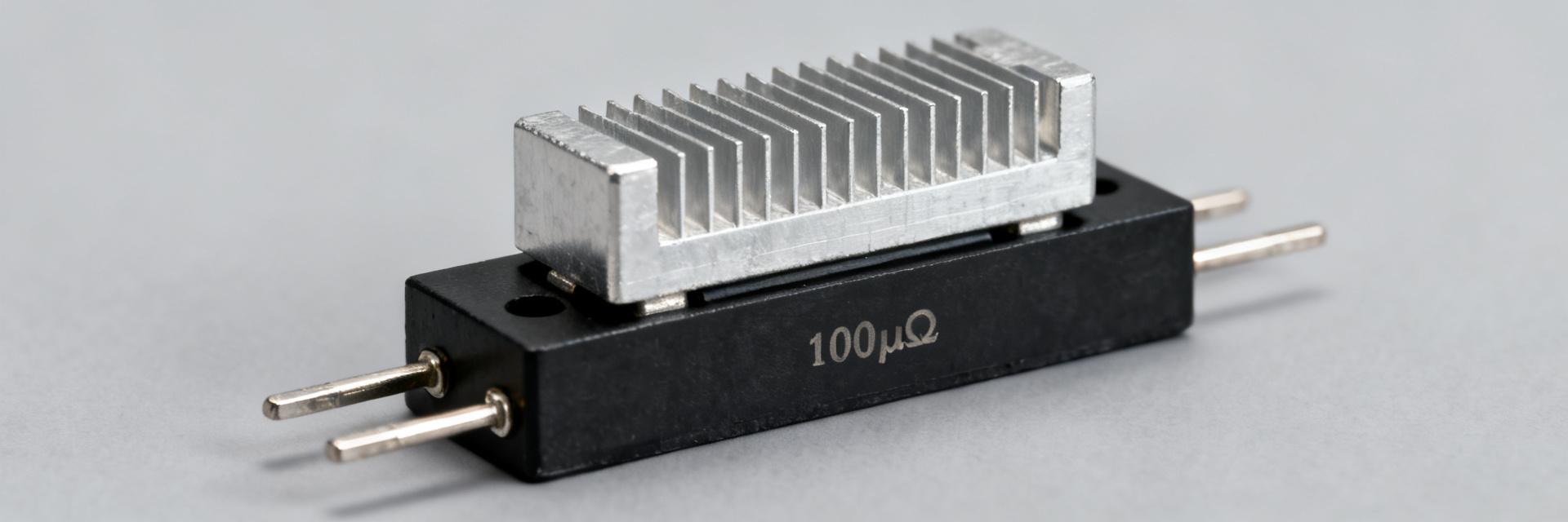
Point: The part number encodes series and value context; the nominal 100 µΩ callout identifies a low-ohm current shunt intended for high-current measurement. Evidence: Typical datasheets place nominal resistance and tolerance in the electrical characteristics table and repeat them in ordering codes. Explanation: For engineers, 100 µΩ plus ±1% implies tight absolute error at the resistor level, but total system accuracy depends on TCR, lead resistance, connector effects and ADC resolution in the measurement chain.
What “HoFL3-6918” and the nominal 100µΩ callout mean
Point: The prefix and suffix indicate series and tolerance; 100 µΩ with ±1% denotes a precision, low-ohm shunt. Evidence: Mechanical drawing and ordering code sections confirm package and tolerance suffixes; the electrical table lists nominal value and guaranteed limits. Explanation: In practice this part serves as a current-sense resistor or low-side shunt; designers must treat it as a precision element where temperature and mounting directly affect reading accuracy and long-term drift.
At-a-glance electrical spec summary to show first
Point: A short checklist consolidates critical values for quick design decisions. Evidence: Typical entries include nominal resistance, tolerance, rated power (50 W), TCR (±50 ppm/°C), operating temperature and thermal resistance. Explanation: Flag any test-condition footnotes—power ratings are usually at specific ambient and mounting conditions; guaranteed values often assume measurement at 25°C with recommended mounting, so conditional notes change usable power and accuracy in real systems.
2 — Resistance behavior, tolerance & stability (data analysis)
Point: Accurate measurement of 100 µΩ requires Kelvin (4-wire) technique and attention to contact and lead resistances. Evidence: At 100 µΩ a 10 A test current produces only 1 mV drop, while 100 A produces 10 mV; ADC noise and lead resistance can easily swamp these signals. Explanation: Use 4-wire wiring, heavy gauge leads for current, and separate sense traces. Plan measurement currents that yield measurable voltage without exceeding power limits or heating the shunt significantly during the test.
Measuring and interpreting 100µΩ resistance values
Point: 4-wire measurement is mandatory for sub-milliohm values. Evidence: Example: at 50 A a 100 µΩ shunt drops 5 mV; at 10 A it drops 1 mV. Explanation: Design fixtures with low thermal EMF connectors, differential amplifiers or precision ADCs with appropriate input filtering, and choose test currents that balance measurement resolution against self-heating. Calibrate out lead and contact offsets before reporting resistance.
TCR and long-term stability implications
Point: A TCR of ±50 ppm/°C means measurable resistance shift across operating range. Evidence: Across a 100°C swing, 100 µΩ changes by about 0.5 µΩ (0.5% of nominal). Explanation: For precision systems, compensate for TCR either electronically (temperature measurement plus correction) or choose measurement windows that minimize thermal gradients; inspect datasheet reliability tests (thermal cycling, load life) to anticipate drift over product lifetime.
3 — Power rating, thermal behavior & environmental limits (data analysis)
Point: The 50 W rating is context-sensitive—usable power depends on ambient, thermal path and mounting. Evidence: Datasheet derating curves (or thermal resistance tables) show how available power drops with higher ambient temperature or poorer heat sinking. Explanation: Treat the 50 W as valid only for the specified mounting and airflow; if mounted on a PCB without thermal vias or copper pours, effective continuous power may be substantially lower and require derating or forced cooling.
Rated power, derating and thermal management
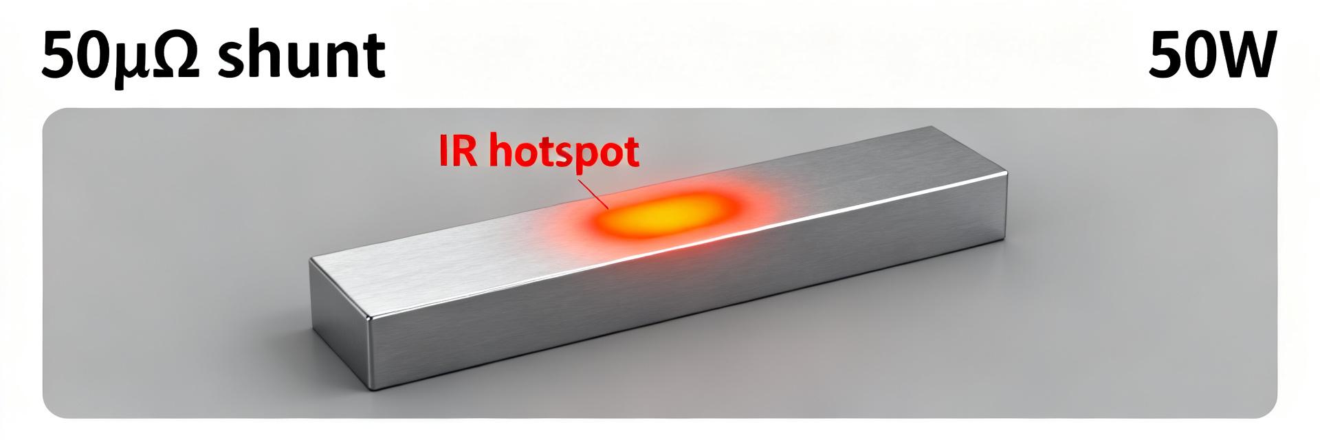
Point: Derating is a function of thermal resistance from resistor to ambient. Evidence: A simple derating example: if datasheet shows 50 W at 25°C ambient and linear derating to zero at 170°C, a 70°C ambient reduces continuous power proportionally. Explanation: Use copper pours, direct heat-sinking, or forced air for sustained high-current applications. Validate with thermal imaging and burn-in under representative conditions to confirm steady-state temperature and derating.
Operating temperature and mechanical/environmental limits
Point: −55°C to 170°C operating range imposes constraints on PCB materials and assembly. Evidence: High-temperature operation affects solder reliability and nearby components; datasheet sections list soldering profiles and mechanical limits. Explanation: Check recommended soldering profiles, torque limits for mounting hardware, and vibration/shock qualifications when the shunt is used in automotive or industrial applications to ensure mechanical and electrical integrity across environments.
4 — How to read the datasheet and test best practices (method guide)
Point: Read electrical characteristics, test conditions, mechanical drawings, thermal data and reliability tests first. Evidence: These blocks reconcile guaranteed vs. typical values and show conditions for ratings. Explanation: When tables present typical and guaranteed columns, prioritize guaranteed values for design limits and use typicals to predict average behavior; annotate any conditional notes and cross-reference mechanical footprint to thermal assumptions.
Datasheet sections you must read first
Point: Prioritize electrical characteristics, test conditions, mechanical drawings and thermal data. Evidence: Test-condition notes reveal temperature and mounting assumptions for power and resistance specs. Explanation: Reconcile differences between typical and guaranteed tables, and extract thermal resistance numbers for use in hand calculations or thermal simulation to size copper areas, heatsinks or airflow for your application.
Practical test setup for 100µΩ shunts
Point: Use a step-by-step 4-wire test workflow with controlled temperature and noise mitigation. Evidence: Checklist items include secure Kelvin clamps, selecting a measurement current that produces millivolt-level signals, low-noise amplifiers, and temperature logging. Explanation: Verify measured resistance, record offset drift vs temperature, perform power dissipation tests and compare results to nominal tolerance and TCR-corrected values; repeatability across samples validates production expectations.
5 — Application examples and quick selection checklist (case + action)
Point: Applications vary: power converters, BMS, motor drives and precision sensing each prioritize different specs. Evidence: Low TCR and tight tolerance favor metrology and BMS accuracy; high power rating favors continuous heavy-current paths in converters or motor drives. Explanation: Map priorities: choose HoFL3-6918 for accuracy-critical, medium- to high-current systems where 50 W and ±1% tolerance match continuous or peak duty, and ensure thermal path meets derating assumptions.
Typical application scenarios and selection guidance
Point: Match spec priorities to application needs. Evidence: For example, battery management demands low TCR for state-of-charge accuracy, while motor controllers need high continuous power and thermal robustness. Explanation: Evaluate trade-offs: tighter tolerance and lower TCR often cost more or require larger packages; confirm the HoFL3-6918 fits the trade between power, size and precision in your system and plan verification tests accordingly.
Quick pre-purchase and verification checklist
Point: A compact engineer checklist reduces selection risk. Evidence: Confirm nominal resistance and tolerance, verify rated power and derating method, validate mechanical footprint and mounting, plan 4-wire test and sample burn-in. Explanation: Execute a short test matrix on representative PCBs with planned thermal management and report measured resistance, temperature coefficient behavior, power dissipation steady-state and any drift after thermal cycling.
Summary
- The HoFL3-6918-C-100uR-1% is a 100 µΩ low-ohm shunt with ±1% tolerance and a 50 W rating; confirm TCR and thermal derating for accuracy-sensitive or high-power use.
- Always measure with 4-wire Kelvin technique and choose test currents that produce millivolt-level signals while monitoring temperature to separate self-heating from intrinsic resistance.
- Validate on a representative thermal fixture: review mechanical drawings, derating notes and reliability tests in the datasheet before final selection to ensure long-term stability.
5 — Common questions and answers
How should I measure the HoFL3-6918 100µΩ resistance accurately?
Use a 4-wire Kelvin fixture with low-thermal EMF connectors, select a measurement current that yields several millivolts of drop without overheating (for example, 10–50 A depending on fixture capability), and use a high-resolution differential ADC or nulling bridge. Log temperature and repeat measurements after thermal equilibrium to report a stable resistance value.
How does TCR affect readings for a 100µΩ shunt?
A TCR of ±50 ppm/°C causes about 0.5 µΩ change per 100°C swing on a 100 µΩ part, roughly 0.5% fractional change. Compensate by measuring local temperature and applying correction, selecting low-TCR parts for high-accuracy systems, or designing to minimize temperature gradients during measurement.
What thermal management is required for continuous 50 W dissipation?
Fifty watts continuous requires a low thermal resistance path to ambient: copper pours with thermal vias, direct heatsinking, or forced air. Use the datasheet’s thermal resistance values to calculate steady-state temperature, and perform burn-in with thermal imaging to confirm that PCB and neighboring components remain within safe temperature limits.
What is the physical significance of the 1% tolerance on the HoFL3-6918?
A 1% tolerance guarantees that the nominal 100 µΩ resistance remains within ±1 µΩ at the calibration temperature (typically 25°C). While this establishes a solid performance baseline, system-level accuracy must account for thermal drift (TCR), mechanical trace misalignments, and connection interface resistance, making 4-wire Kelvin tracking absolutely mandatory.