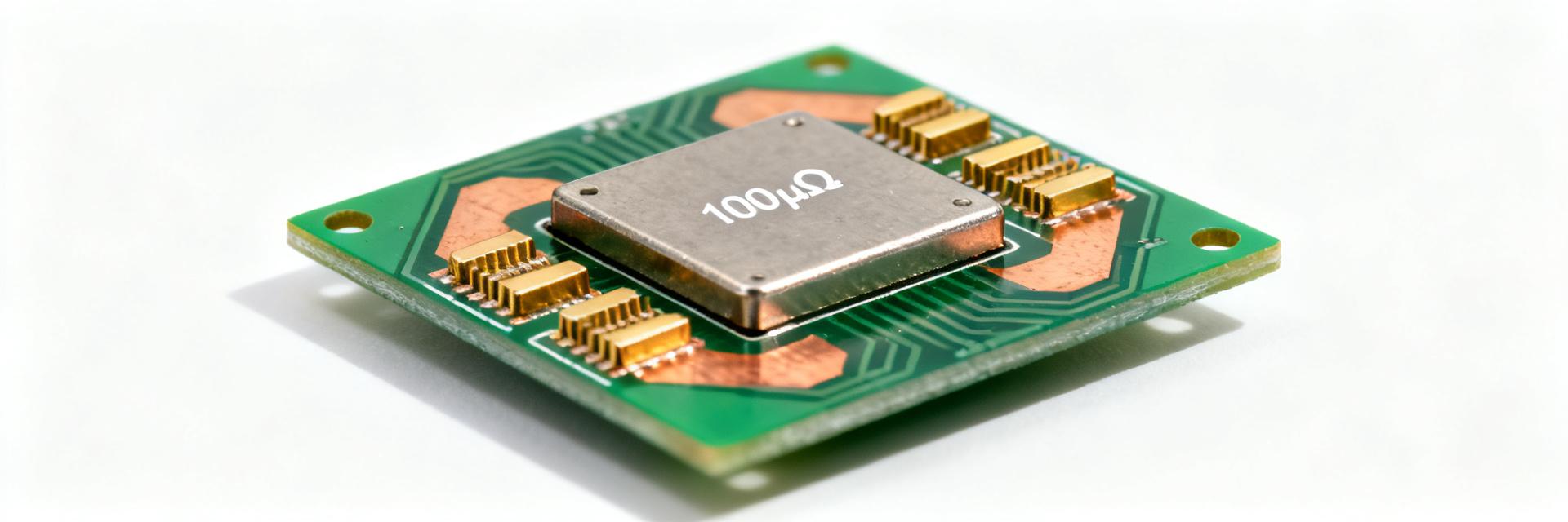
100µΩ Shunt Resistor Report: Precision Specs & Test Data
Demand for sub‑milliohm current sensing has risen sharply in high‑power battery systems and power conversion equipment; designs increasingly require 100µΩ shunt resistor measurements with millivolt‑level drops at hundreds of amps. This report gives a hands‑on, data‑backed guide: spec breakdowns, practical datasheet checks, reproducible lab test procedures, sample result templates, and a checklist to move from evaluation to production.
The document defines what a 100µΩ device is in practice, explains why low resistance matters for high‑current accuracy, and delivers concrete examples (e.g., at 100 A: Vdrop = 10 mV, P = 1.0 W). Readers will get a usable checklist, sample tables for Vdrop vs current and ΔR vs temperature, and troubleshooting guidance for common anomalies.
1 — Background: What "100µΩ shunt resistor" means in practice
Definition & typical use cases
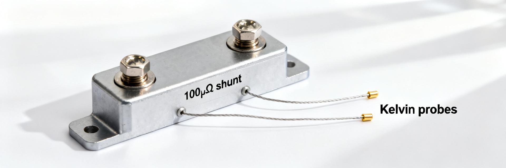
100 µΩ equals 0.0001 ohm; these parts are used where currents range from tens to thousands of amps and voltage sensing must not appreciably load the circuit. For intuition: 50 A → 5.0 mV, 100 A → 10.0 mV, 500 A → 50.0 mV; power scales as I²R. Precision shunt use cases include battery SOC sensing, EV charging measurement, motor drives, and inrush detection.
Typical construction & materials overview
Common constructions: metal‑strip (stamped copper/bronze), manganin or constantan foil, welded tab assemblies, and PCB shunts. Materials trade off TCR, mechanical robustness, and power handling; typical TCR ranges are tens to a few hundred ppm/°C depending on alloy. Recommended callouts: schematic/photo of foil shunt with welded Kelvin tabs and expected TCR ranges in caption.
2 — How to read a shunt resistor datasheet (practical datasheet checklist)
Key electrical specs to verify
Essential fields: nominal resistance, tolerance, TCR (ppm/°C), continuous power/current rating, pulse/overload rating, thermal resistance, frequency response, and specified ambient/test conditions. For a precision 100µΩ device expect tight tolerance (≤1%), low TCR (preferably <±150 ppm/°C), clear pulse ratings, and thermal resistance data so you can compute self‑heating effects on accuracy.
| Must‑check | Nice‑to‑have |
|---|---|
| Nominal R & tolerance | Frequency response / inductance |
| TCR (ppm/°C) | Extended temperature characterization |
| Continuous and pulse current ratings | Matched reference resistor options |
| Thermal resistance / temp rise data | Qualified reliability tests |
Mechanical & mounting specs that affect measurement
Mechanical details—Kelvin terminal geometry, recommended torque, lead length, and mounting method—directly affect measurement. Use 4‑wire connections, keep sense leads short and thermally isolated, and follow torque specs to avoid strain‑induced resistance change. Environmental IP ratings and shock specs matter for field deployments; poor mechanical coupling can introduce error through inconsistent thermal paths.
3 — Precision & thermal performance: data analysis you should include
TCR, drift, and thermal EMF: measurement and interpretation
TCR in ppm/°C translates to fractional change per degree: example, a device with ±150 ppm/°C over ΔT = 50°C shifts by 150×50 = 7,500 ppm (0.75%), so a 100µΩ part changes by 0.75µΩ. Long‑term drift and thermal EMF from dissimilar metals can add tens to hundreds of µV at milliohm‑level Vdrops; acceptance criteria for high accuracy are typically TCR <±150 ppm/°C and low thermal EMF.
Power dissipation, self‑heating curves and derating
Self‑heating follows P = I²R; at 100 A a 100µΩ shunt dissipates 1 W. Use thermal resistance (°C/W) from the datasheet to predict temperature rise: e.g., 10 °C/W × 1 W → 10 °C rise. Derate continuous current to keep steady‑state temperature within rated limits and follow pulse vs continuous ratings; present ΔR (%) vs power to quantify accuracy loss under load.
4 — Test methodology: reproducible lab procedures for 100µΩ shunts
Recommended test setup & equipment
Required gear: precision current source or programmable load, low‑noise nanovoltmeter or high‑resolution ADC, 4‑wire Kelvin fixturing, temperature chamber or controlled heatsink, and data logger. Setup checklist: warm up source, zero offset, ensure guarded low‑EMF connections, average multiple readings, and record ambient and shunt temperatures for each point to correlate ΔR with thermal state.
Measurement routines & uncertainty analysis
Test sequences: DC V–I sweeps at 10%, 25%, 50%, 75%, 100% rated current plus overload pulses; thermal soak tests and TCR runs. Quantify uncertainty components (instrument accuracy, contact repeatability, thermal EMF, noise) and combine them (RSS) to report expanded uncertainty with coverage factor k=2. Provide a tabular test plan and sample reporting template for repeatability.
5 — Real test data & example case studies (how to present results)
Example dataset: bench test of a 100µΩ shunt (recommended figures/tables)
Present raw Vdrop vs current, computed R = V/I, percent deviation from nominal, ΔR after thermal soak, and TCR fit. Example summary: measured R range 98–102 µΩ across tests, derived TCR ~120 ppm/°C. Include Vdrop vs current and ΔR vs temperature plots with labeled axes; offer CSV template with columns: current, Vdrop, measured_R, ambient_T, shunt_T, notes.
Interpreting anomalies & troubleshooting notes
Frequent anomalies: elevated ΔR due to contact heating, apparent resistance shifts from poor Kelvin wiring, thermal EMF when copper‑to‑thermocouple junctions exist, or solder joint resistance. Troubleshooting: verify Kelvin wiring, reapply torque to terminals, isolate thermal gradients with matched fixtures, and rerun repeatability tests. A short decision tree helps isolate contact vs bulk resistance causes.
6 — Selection & implementation checklist: from datasheet to production
How to choose the right 100µΩ shunt for your design
Selection criteria: continuous and pulse current handling, tolerance, TCR, package and mounting, thermal path to heat sink, and accuracy budget vs ADC resolution. For procurement use a shunt resistor datasheet checklist: for battery SOC at 200 A prioritize low TCR and tight tolerance; for motor control prioritize pulse rating and mechanical robustness. Include cost/availability in final tradeoff.
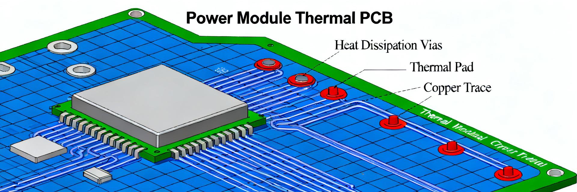
PCB/layout, calibration & BOM integration tips
Layout: separate heavy current traces from Kelvin sense routes, place sense pads close to shunt terminals, and avoid vias in sense paths. Calibration: implement offset and gain calibration against a reference resistor, store per‑unit calibration constants, and add test points for QC. Recommend scheduled recalibration intervals for high‑precision systems based on operating temperature and duty cycle.
Summary
This report showed how to interpret specs for a 100µΩ shunt resistor, which electrical and mechanical datasheet fields matter most, and which lab tests prove thermal and precision performance. Actionable next steps: run the recommended V–I and thermal sequences, use the procurement checklist, and document combined measurement uncertainty before approving production parts.
- Check nominal R, tolerance, and TCR on the datasheet; confirm continuous and pulse current ratings against your worst‑case duty cycle (include expected Vdrop and power dissipation calculations for accuracy budgeting).
- Use Kelvin 4‑wire connections, short sense leads, and guard wiring in the lab; log ambient and shunt temperatures for every measurement to separate thermal effects from electrical drift.
- Adopt the suggested test plan: V–I sweeps at fractional ratings, thermal soak tests, and pulse testing; compute combined uncertainty (k=2) and apply derating rules for steady‑state thermal limits.
FAQ
How is a 100µΩ shunt resistor used for high‑accuracy current sensing?
Use a 4‑wire Kelvin connection and measure the millivolt Vdrop with a low‑noise nanovoltmeter or high‑resolution ADC; choose ADC range and input conditioning so quantization and input noise are small relative to the expected Vdrop. Calibrate for offset and gain against a known reference and track temperature to correct TCR‑induced shifts.
What are the key tests to validate a 100µΩ shunt resistor for production?
Validate with DC V–I sweeps at defined points (10–100% rated current), thermal soak tests to extract TCR, pulse overload checks, and repeatability runs. Record ambient and shunt temperatures, compute ΔR vs power, and report expanded uncertainty (k=2); include pass/fail criteria tied to your system accuracy budget.
How do I mitigate thermal EMF and contact errors when measuring low resistances?
Mitigate thermal EMF by using matched alloys in fixtures, avoid dissimilar‑metal junctions in the low‑level measurement path, and stabilize temperatures before readings. Ensure clean, properly torqued Kelvin connections, use guarding and differential measurement techniques, and average multiple readings to reduce noise and transient offsets.
What layout and calibration practices are recommended for PCB integration?
Separate heavy current traces from Kelvin sense routes, placing sense pads close to the shunt terminals. Implement offset and gain calibration against a reference resistor, store per-unit calibration constants, and schedule calibration intervals based on operating temperatures.