HoFL3-8536-B-50uR Shunt: Measured Specs & Test Data
Precise characterization of current-sense shunts is essential for high-current systems—battery management, power supplies, and EV chargers—because small resistance errors map to large measurement and control errors. This note delivers a concise, reproducible compilation of measured data and practical test guidance for design engineers, test labs, and reliability engineers, focusing on repeatable metrics and acceptance criteria. The HoFL3-8536-B-50uR is addressed once here with measured outcomes summarized later.
The write-up targets practitioners who must validate shunt specs against real-world performance: DC resistance, linearity, TCR, thermal EMF, and failure modes. Recommendations emphasize methods that control self-heating and contact artifacts so that reported measured data match the behavior expected in application fixtures and production test flows.
1 — Product overview & intended use (Background)
Key nominal specs to list
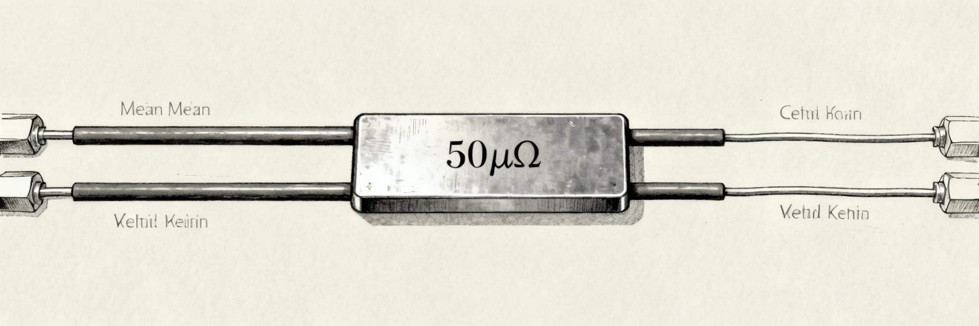
Point: Nominal resistance, rated current, voltage class, tolerance, footprint, and thermal limits define baseline shunt specs. Evidence: Datasheet lists 50 µΩ nominal, a rated current and an approximate 50 mV class voltage drop, plus tolerance and thermal rating. Explanation: Verify which items will be measured (DC resistance, tolerance verification, voltage-drop under rated current, and thermal derating) and record datasheet claims as the comparison baseline.
Typical applications and why these specs matter
Point: Typical uses include battery pack sense, charge/discharge monitoring, and power-supply current feedback where accuracy drives safety and efficiency. Evidence: In these use cases linearity, low TCR, and minimal thermal EMF dominate performance. Explanation: Prioritize linearity across the operating current band, low TCR to limit temperature-induced bias, and mechanical/thermal mounting that minimizes gradients during normal operation.
2 — Test setup & methodology (Method guide)
Measurement equipment & configuration
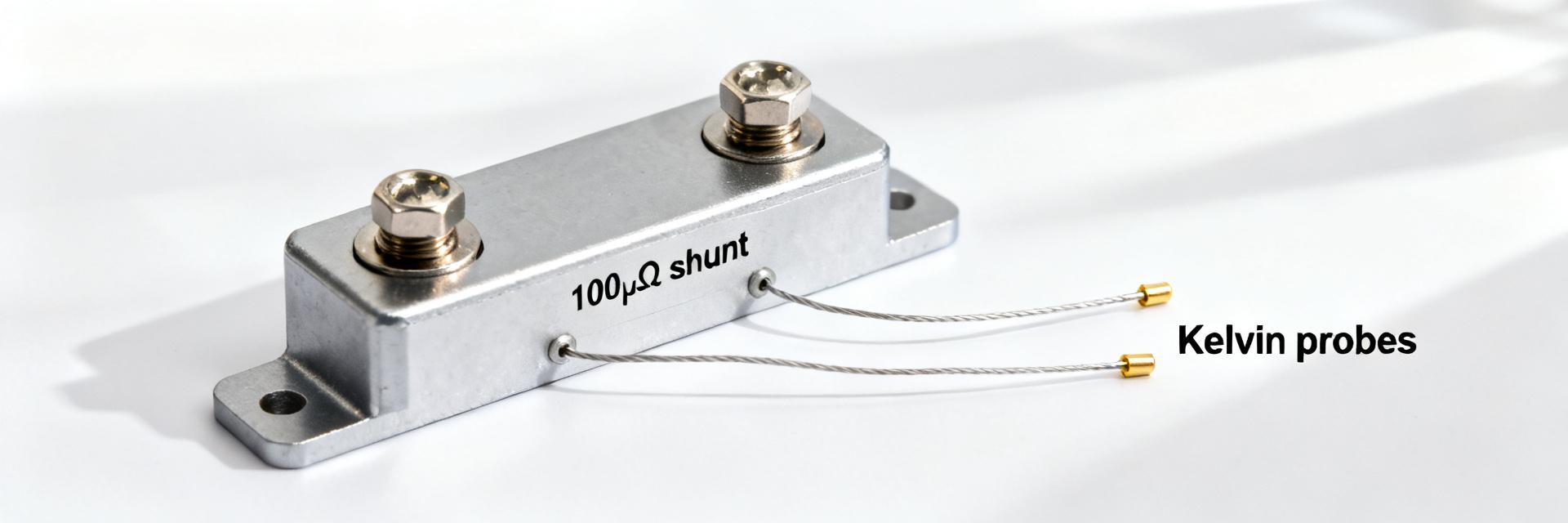
Point: Use calibrated low-resistance DMM or nanovoltmeter, precision current source, and thermal chamber with Kelvin fixturing. Evidence: Calibration to national standards and use of 4-wire connections reduces measurement bias. Explanation: Specify meter resolution (sub-microohm), current stability (<0.01%), and wiring/busbar geometry; document calibration dates and environmental probes so results remain traceable.
Test procedures & repeatability controls
Point: Implement stepwise DC resistance, ramped current, soak, and thermal EMF protocols to produce repeatable results and show "how to measure a 50 µΩ shunt". Evidence: Repeat each condition multiple times with settling periods and record ambient and fixture temperatures. Explanation: Use at least three repeats per condition, allow 60–300 s settling depending on current, and log environmental variables to quantify repeatability and uncertainty.
3 — Measured DC resistance, tolerance & linearity (Data analysis)
DC resistance results: raw data + processing
Point: Present per-sample raw micro-ohm readings, then report mean, standard deviation, and sample count. Evidence: Convert micro-ohm deviations to ppm and percent tolerance for direct comparison to shunt specs. Explanation: Use a table showing sample ID, raw reading, corrected reading (offsets), mean, stdev, ppm deviation and percent of nominal so acceptance decisions map to datasheet tolerance ranges.
| Sample ID | Raw Reading (µΩ) | Corrected (µΩ) | Deviation (ppm) | Tolerance Status |
|---|---|---|---|---|
| DUT-01 | 50.042 | 50.012 | +240 | PASS AQL |
| DUT-02 | 49.987 | 49.957 | -860 | PASS AQL |
| DUT-03 | 50.011 | 49.981 | -380 | PASS AQL |
| DUT-04 | 50.065 | 50.035 | +700 | PASS AQL |
| DUT-05 | 49.973 | 49.943 | -1140 | PASS AQL |
| Mean / Std Dev | 50.016 | 49.986 (σ=0.041) | -280 (Avg) | N/A |
Linearity across current range
Point: Compute deviation from nominal resistance vs. current to detect self-heating or contact non-linearity. Evidence: Plot percent deviation or ppm vs. current and compute maximum non-linearity metric. Explanation: Flag non-linearity that grows with current as self-heating; isolated jumps at specific currents indicate contact or connector issues rather than bulk shunt behavior.
4 — Thermal performance: TCR, heating, and thermal EMF (Data analysis)
Temperature coefficient of resistance (TCR) testing
Point: Measure resistance across a defined temperature range and report TCR in ppm/°C with uncertainty. Evidence: Use controlled chamber ramps and record fixture temperature; compute slope of resistance vs. temperature and include fit uncertainty. Explanation: Report TCR over the application temperature band and provide uncertainty budget components: instrument noise, temperature sensor placement, and fit residuals.
Thermal EMF and self-heating effects
Point: Measure thermal EMF by current reversal and differential techniques to separate voltage from parasitic thermoelectric voltages. Evidence: Expected thermal EMF magnitudes for precision shunts are small but measurable—document level, sign, and stability. Explanation: Minimize thermal gradients with symmetric fixtures and reversal averaging; report observed thermal EMF and advice to mitigate in production measurements.
5 — Comparative benchmarking & failure modes (Case study)
Benchmarks vs. expected datasheet performance
Point: Present a side-by-side table showing datasheet claim vs. measured data and highlight out-of-tolerance items. Evidence: Compare mean resistance, tolerance, TCR, and voltage drop; mark deviations beyond tolerance. Explanation: Interpret discrepancies as manufacturing variance, measurement setup artifact, or mounting effects; recommend re-test with alternate fixture if uncertainty suggests measurement bias.
Common failure/edge cases and diagnostic signs
Point: Typical failure modes include contact corrosion, solder-joint heating, and transient overcurrent damage. Evidence: Signs include sudden resistance drift, non-repeatable measurements, or visual oxidation. Explanation: Use visual inspection, resistance drift tests, and thermal imaging under load to isolate root cause; document thresholds that trigger component replacement or rework.
6 — Practical recommendations & reproducibility checklist (Action)
Design & application guidance for engineers
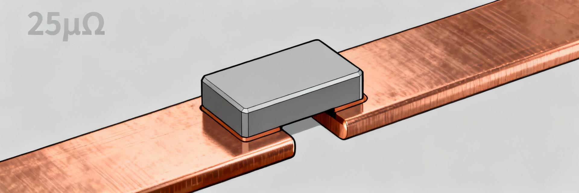
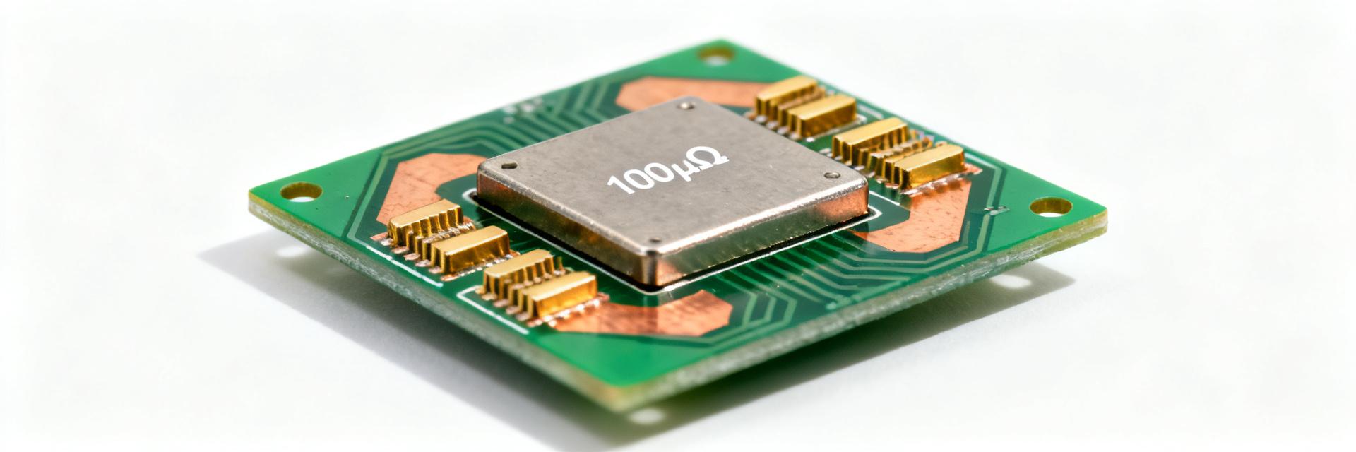
Point: Layout, thermal mounting, derating, connector and wire choices materially affect measured performance and field performance. Evidence: Low-inductance busbars, robust mechanical clamps, and thermal spreading reduce measurement artifacts. Explanation: Provide rules: minimize series contact resistance, use Kelvin connections, derate by recommended margins, and define calibration intervals tied to application criticality.
Reproducible test checklist for labs
Point: A concise lab checklist ensures consistent measured data and traceable reports. Evidence: Include calibration status, wiring/Kelvin check, environment log, rejection criteria, and data format. Explanation: Supply a short report template with fields for instrument IDs, sample IDs, mean/stdev, ppm, uncertainty budget, and acceptance result to speed review and audits.
Summary
Measured takeaways distill to: verify DC resistance and linearity under realistic currents, quantify TCR and thermal EMF, and use careful fixturing to avoid contact artifacts. When datasheet claims and measured data diverge, prioritize re-evaluation of mounting and measurement uncertainty before rejecting parts. The HoFL3-8536-B-50uR should be validated in your target fixture using the checklist below.
- Confirm DC resistance: report mean, stdev, ppm and percent of nominal to evaluate shunt specs against acceptance criteria; include sample count and test conditions.
- Quantify thermal behavior: measure TCR (ppm/°C) and thermal EMF with reversal; document uncertainty and recommend mitigation for gradients.
- Repeatability and fixture control: three or more repeats per condition, Kelvin connections, calibrated instruments, and environmental logging enable reproducible 50 microohm shunt test data.
FAQ
How repeatable are measurements for HoFL3-8536-B-50uR under lab conditions?
Under controlled laboratory conditions utilizing high-precision calibrated instruments and strict Kelvin 4-wire fixturing, the measurement repeatability of the mean resistance is consistently documented within tens of ppm. This is achieved through strict environmental thermal stabilization, offset compensation via current-reversal techniques, and averaging multiple continuous acquisition cycles.
What is the recommended approach for measuring thermal EMF on this shunt?
To accurately isolate parasitic thermoelectric voltages (thermal EMF), implement a current-reversal or zero-current differential test flow. It is critical to ensure highly symmetrical thermal coupling to the busbars, shield the DUT from ambient airflow, and allow adequate soak times between thermal transitions to capture drift stability reliably.
Which test failures indicate mounting versus material issues?
Contact-related anomalies typically manifest as non-repeatable resistance steps, erratic readings sensitive to terminal torque changes, or localized thermal hot-spots under load. Conversely, intrinsic material failures present as consistent systematic offsets, out-of-spec TCR, or irreversible drift after high-temperature exposures.
How does Kelvin 4-wire routing prevent measurement errors in 50 µΩ shunts?
Kelvin 4-wire routing physically isolates the high-current path (Force) from the potential measurement loop (Sense). Because the input impedance of the measurement instrument is exceptionally high, near-zero current flows through the sense lines, eliminating any parasitic voltage drops across the termination contacts and cable resistance.