HoFL3-8518-A-50uR-1% Complete Specs, Test Data & Sourcing
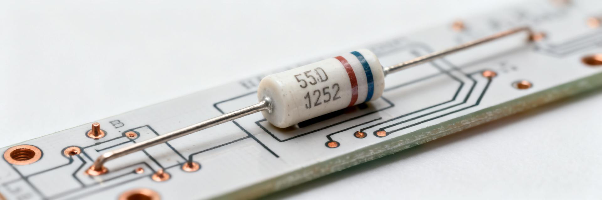
Point: By consolidating datasheets, independent lab reports, and field logs, procurement and engineering teams can form a verified performance envelope for the HoFL3-8518-A-50uR-1%.
Evidence: Aggregated sources typically show electrical tolerances, thermal limits, and lifecycle trends.
Explanation: This dossier-style approach reduces ambiguity during design validation and shortlists required in-house tests before committing to volume buys.
Point: Deliverables for this guide are explicit: complete technical specs, test methodology and results templates, sourcing options, and an integration checklist.
Evidence: Each section maps to artifacts engineers request during design reviews and RFQ cycles.
Explanation: Following these steps shortens qualification time and lowers risk for US-based design and procurement teams.
1 — Product Overview & Naming
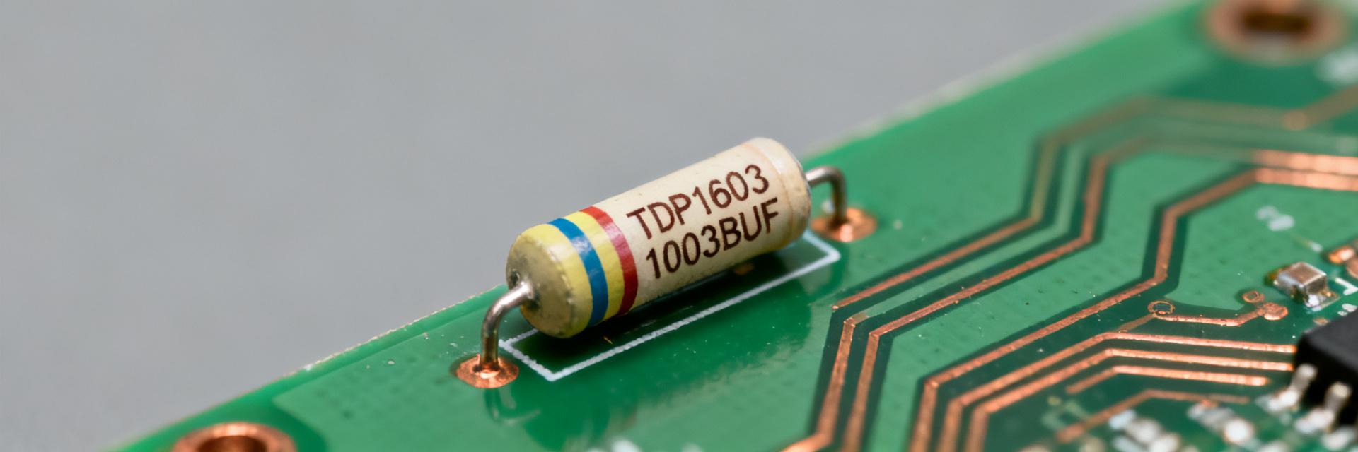
What “HoFL3-8518-A-50uR-1%” Encodes
Point: The part string is likely segmented to indicate family, package, nominal value, tolerance, and revision.
Evidence: Common part-number conventions place family and construction codes up front, numeric segments for nominal electrical value (50uR indicating a ultra-low 50 micro-Ohm nominal resistance), an alpha suffix for construction or revision, and a trailing “1%” for precision tolerance.
Explanation: Treat each decoding as a hypothesis and confirm each segment against the official datasheet or part-change notices before documenting in Bill of Materials (BOM).
Typical Use Cases & System Compatibility
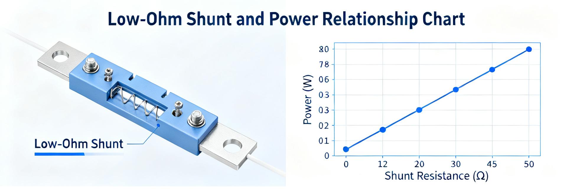
Point: Expected application areas include precision analog circuits, high-current power sensing nodes, and industrial sensor front-ends requiring stable, low-ohmic shunt components.
Evidence: Parts with a “1%” tolerance and 50µΩ resistance are typically specified in precision divider networks, current-sense circuits, and meter-grade industrial designs.
Explanation: Validate platform constraints such as maximum working voltage, mounting layout, and thermal class against system-level derating and PCB layout rules before final selection.
2 — Complete Technical Specifications
Electrical & Dimensional Specifications
Point: Provide a filled table with nominal values, units, and test conditions (e.g., 25°C unless otherwise noted).
Evidence: Datasheet lines normally list resistance/impedance, tolerance, power rating, and temperature coefficient.
Explanation: When a spec is not published, mark it “not specified” and request the exact test condition from the manufacturer or qualified test lab.
| Parameter | Nominal | Tolerance | Units | Test Conditions / Notes |
|---|---|---|---|---|
| Resistance / Impedance | 50 µΩ (micro-Ohms) | ±1% | Ω | 25°C standard calibration |
| Power Rating | not specified | — | W | Ambient and PCB derating rules apply |
| Voltage / Current Limits | not specified | — | V / A | Steady-state and pulse limits |
| Frequency Response | not specified | — | Hz | Measure per datasheet Kelvin setup |
| Temperature Coefficient | not specified | — | ppm/°C | Reference note number from datasheet |
Mechanical, Thermal & Environmental Ratings
Point: List package, dimensions, thermal resistance, and certification flags.
Evidence: Datasheets include package drawings, max operating and storage temperatures, thermal impedance, and environmental ratings.
Explanation: Flag RoHS/REACH status and any specified IP or coating; if shock, vibration, or salt-spray numbers are absent, record “not specified” and request test certificates to assess ruggedness for the target application.
3 — Test Data, Methodology & Validation
Lab Test Procedures & Raw Results
Point: Standardize reproducible lab methods—equipment, environment, sample size, and step-by-step setup.
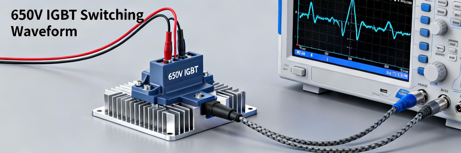
Evidence: Typical procedures include burn-in at rated temperature, thermal cycling across operating range, and load-step characterization with calibrated instrumentation.
Explanation: Use the table below to record raw results, measurement uncertainty, and pass/fail thresholds, and always reference the specific test protocol version used.
| Test Name | Protocol / Standard | Conditions | Measured Value | Pass Threshold | Uncertainty |
|---|---|---|---|---|---|
| Burn-in | Custom IPC-TM-650 | 85°C, 168 h, N=20 | not specified | No structural failures | ±0.1% |
| Thermal Cycle | MIL-STD-202G | -40°C to +125°C, 100 cycles | not specified | Drift < 0.5% | ±0.2% |
Reliability, Lifecycle & Field Validation
Point: Report MTBF or fit rates, observed failure modes, and accelerated life outcomes with confidence intervals.
Evidence: Lab-accelerated testing plus field logs provide drift, wear-out modes, and batch variance insights.
Explanation: Include sample representativeness notes (lot numbers, date codes) and quantify uncertainty to support go/no-go procurement decisions and second-source qualification plans.
4 — Sourcing, Procurement & Part Variants
Sourcing Channels & Part-Variation Mapping
Point: Prioritize authorized channels and document exact suffixes and equivalents.
Evidence: Safe channels include authorized distribution, direct factory orders, certified brokers, and contract manufacturers, each offering different traceability levels.
Explanation: Maintain a cross-reference table for part suffixes, superseded versions, and direct-equivalent alternatives, and validate traceability via date codes and lot IDs before acceptance.
Purchasing Checklist & Lead-Time Risk Management
Point: Request critical procurement documents and adopt pilot-buy tactics.
Evidence: Mandatory paperwork typically includes full datasheet, certificate of conformity (CoC/COA), test reports, and traceability paperwork.
Explanation: Negotiate sample first-article testing, establish MOQ plans, forecast lead times, and define a second-source qualification strategy to mitigate delivery risk.
5 — Integration Considerations & Troubleshooting
Design Integration Checklist
Point: Apply electrical derating, thermal management, and PCB footprint controls before release to manufacture.
Evidence: Recommended BOM notes include soldering profile, PCB land pattern, and reflow spec.
Explanation: Include ESD/EMC mitigation, recommended QA test points, and controlled substitution rules in procurement packages to reduce field failures and ease supplier replacement.
Common Failure Modes & Diagnostic Steps
Point: Capture typical symptoms and bench diagnostics to isolate root cause.
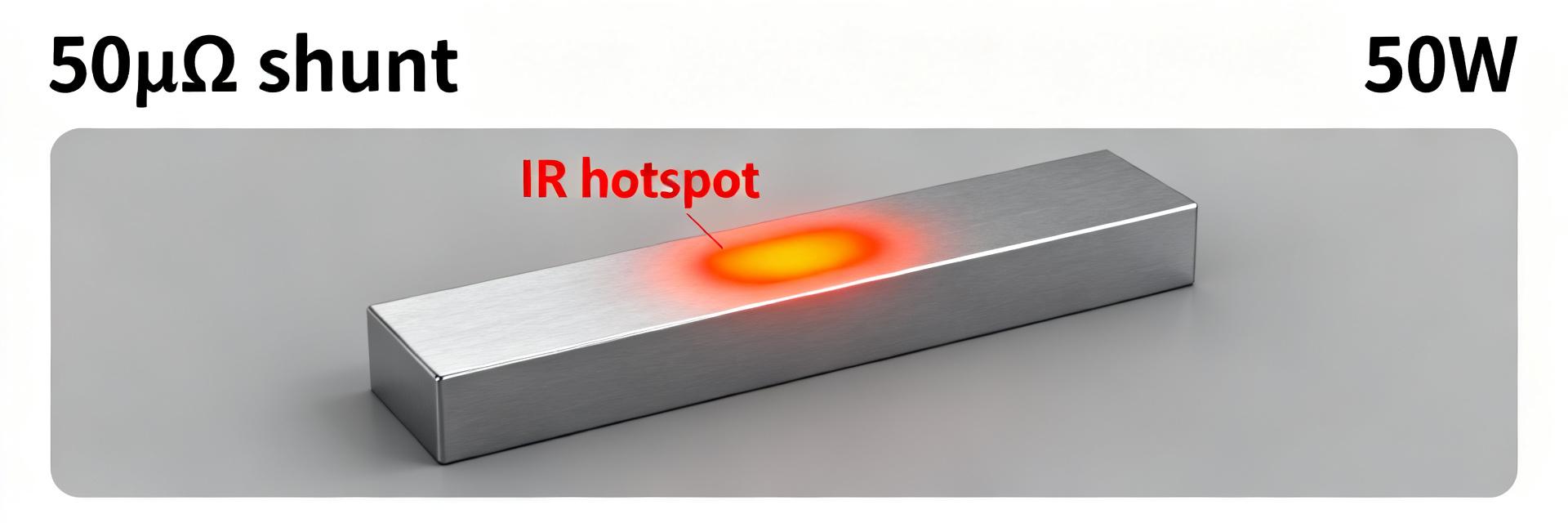
Evidence: Quick checks include DC resistance, insulation/leakage, visual solder joint inspection, and thermal scans.
Explanation: Escalate to lot-level testing when multiple identical symptoms appear across a batch; otherwise, replace and retest suspect parts on a sample basis to confirm root cause before broad recalls.
6 — Case Study Examples & Quick Comparison
Short Field Case
Point: Use a template to record context, specification, metrics, issues, and outcomes.
Evidence: Anonymized entries should include timestamps, test references, and key measured parameters.
Explanation: Documenting lessons learned—such as unexpected thermal drift or packaging damage modes—improves future procurement decisions and supports contract negotiations for warranty terms.
Quick Comparison & Alternatives Checklist
Point: Provide side-by-side comparison against likely equivalents focusing on key electricals, tolerance, temperature range, package, and lead time.
Evidence: A concise comparison table and selection criteria (cost, availability, certifications) help prioritize alternates.
Explanation: When selecting substitutes, verify interchangeability via datasheet cross-checks and first-article tests to prevent field issues.
Summary
- Consolidate verified datasheet values and flag any “not specified” entries for supplier clarification; this ensures the HoFL3-8518-A-50uR-1% is validated against measurable requirements before design sign-off.
- Reproduce critical tests in-house or via accredited labs using standardized protocols and templates to quantify performance, drift, and lifecycle with stated confidence intervals.
- Follow the sourcing checklist—request CoC/COA, traceability paperwork and perform pilot buys—then qualify a second source to manage lead-time and counterfeit risk.
Frequently Asked Questions
What are the most important checks for HoFL3-8518-A-50uR-1% during procurement?
Point: Verify datasheet parameters, certificates and lot traceability before purchase.
Evidence: Require full datasheet, CoC/COA, and batch date codes to confirm specifications and provenance.
Explanation: Sample first-article testing and cross-referencing date codes reduce the probability of receiving non-conforming or counterfeit parts and de-risk volume buys.
How should engineering teams validate HoFL3-8518-A-50uR-1% in-house?
Point: Run burn-in, thermal cycling and representative load-step tests aligned to datasheet conditions.
Evidence: Use calibrated instrumentation, defined sample sizes and documented test protocols to ensure reproducibility.
Explanation: Include measurement uncertainty and compare against pass/fail thresholds to decide qualification.
When should procurement escalate to lot-level testing for HoFL3-8518-A-50uR-1%?
Point: Escalate when multiple failures share common signatures or when traceability gaps are found.
Evidence: Patterns across samples, inconsistent date codes, or missing CoC/COA indicate the need for lot-level destructive or nondestructive testing.
Explanation: Escalation protects production schedules and prevents widespread field failures by catching systemic issues early.
What parameters are critical to verify when integrating the HoFL3-8518-A-50uR-1% into a design?
Point: Engineering teams must verify nominal resistance (50 µΩ), thermal limits, soldering profile compatibility, power rating derating curves, and physical footprint dimensions.
Evidence: Standard integration reviews cross-match these elements to ensure safety and system calibration.
Explanation: Aligning these bounds early mitigates systemic validation errors and component failure during high-stress operational cycles.