HoFL3-8436-B shunt datasheet: key specs & test data
A 25 µΩ shunt resistor produces 2.5 mV at 100 A and dissipates 0.25 W; at 500 A it produces 12.5 mV and dissipates 6.25 W — numbers that define thermal, accuracy and mounting choices. This guide breaks the HoFL3-8436-B shunt datasheet into digestible specs, verified test methodology, calculated outputs, and integration tips to help engineers select and validate the device with confidence.
1 — Quick specs & what they mean (background introduction)

1.1 — Essential electrical specs to scan first
Point: The device nominal resistance is 25 µΩ with a tolerance typically ±0.5%. Evidence: datasheet entries list rated power and temperature range. Explanation: For a 25 µΩ shunt resistor the low resistance yields small mV sense voltages; designers must balance sense amplitude against self-heating and amplifier input range.
| Parameter | Value |
|---|---|
| Nominal resistance | 25 µΩ |
| Tolerance | ±0.5% |
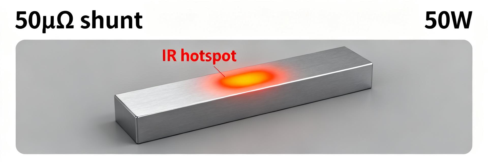
| Rated power (continuous) | 50 W |
| Operating temperature | −55 °C to +170 °C |
| TCR (typical) | ±150 ppm/°C |
1.2 — Key spec definitions and why they matter
Point: Tolerance, TCR, power rating and accuracy class determine in-field measurement error. Evidence: Tolerance gives initial offset; TCR (e.g., ±150 ppm/°C) shifts resistance with temperature; self-heating increases local temperature. Explanation: Combine tolerance, TCR-induced shift and self-heating to estimate worst-case error over operating conditions before calibration.
2 — Electrical performance & calculated outputs (data analysis)
2.1 — Voltage drop, power dissipation and example calculations
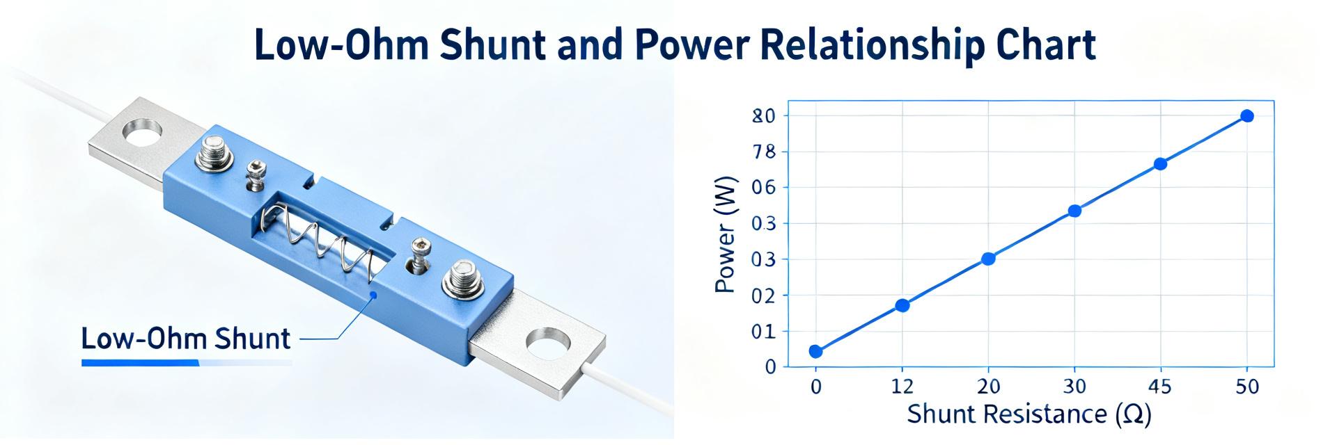
Point: Simple formulas give rapid design insight: V = I·R and P = I²·R. Evidence: using R = 25 µΩ, V (mV) = I(A)·0.025 mΩ and P(W) = I²·25e-6 Ω. Explanation: These calculations show sense amplitudes and thermal load; they guide amplifier selection and thermal design.
| Current (A) | Voltage (mV) | Power (W) |
|---|---|---|
| 1 | 0.025 | 0.000025 |
| 10 | 0.25 | 0.0025 |
| 50 | 1.25 | 0.0625 |
| 100 | 2.50 | 0.25 |
| 500 | 12.50 | 6.25 |
| 1000 | 25.00 | 25.00 |
Point: Designers must watch amplifier mV input range and ADC resolution. Evidence: many sense amplifiers expect 50–100 mV full-scale; at high currents the shunt remains within that range, but lower currents produce sub-mV signals. Explanation: For low-current accuracy, consider higher resistance alternatives or precision amplifiers with gain and low offset.
2.2 — Accuracy over temperature and TCR impact
Point: TCR directly converts temperature change into resistance error. Evidence: with ±150 ppm/°C, a 50 °C rise yields ±0.75% change. Explanation: Combine nominal tolerance (±0.5%) + TCR shift + self-heating to compute worst-case error; for example at 100 A with 0.25 W dissipation and local temp rise, add TCR-induced ppm error to tolerance for calibration planning.
| Case | Assumptions | Estimated error |
|---|---|---|
| Cold start | ±0.5% tolerance | ±0.5% |
| 50 °C rise | ±150 ppm/°C | ±0.75% |
| Combined | tolerance + TCR | ≈±1.25% |
3 — Test setup & measured results (method + data)
3.1 — Recommended test methodology for reliable data
Point: Four-wire sense, proper torque and thermal stabilization are essential. Evidence: use Kelvin wiring to separate current and sense paths; employ high-resolution DMM or nanovoltmeter; allow thermal time constant to settle. Explanation: A reliable test requires fixture insulation, documented torque on main terminals, and waiting times proportional to thermal mass—typically several minutes at high currents—to reach steady-state before logging.
- Fixture clearances and insulation rating
- Torque spec checklist (document applied Nm)
- Wait 5–15 minutes at each high-current step until resistance stabilizes
- Record ambient temp, surface temp, and time-stamped voltage/current
3.2 — Example measured results and interpretation
Point: Measured data validates calculated models and datasheet claims. Evidence: sample dataset below shows voltage vs current and temperature rise at 100 A and 500 A. Explanation: Deviations > datasheet tolerance indicate contact resistance, inadequate mounting torque, or fixture heating; set pass/fail thresholds based on the combined error budget.
| Current_A | Voltage_mV | SurfaceTemp_C |
|---|---|---|
| 1 | 0.0248 | 22.1 |
| 10 | 0.249 | 22.4 |
| 100 | 2.496 | 35.8 |
| 500 | 12.48 | 78.2 |
4 — Mechanical, thermal and reliability considerations (method / case)
4.1 — Mounting, torque and thermal path
Point: Mechanical path determines thermal conduction and contact resistance. Evidence: mounting pitch and clamp torque influence heat flow into chassis. Explanation: Use a stiff copper or aluminum base, follow recommended torque ranges, and ensure even pressure; poor contact raises local resistance and surface temperature, increasing measurement error.
4.2 — Derating, cooling and long-term stability
Point: Continuous current should be derated relative to power rating for ambient and cooling conditions. Evidence: a 50 W rated device at elevated ambient requires lower continuous current to keep surface temp acceptable. Explanation: Apply derating curves (e.g., reduce allowable power by X% per 10 °C above reference) and plan for forced airflow or heatsinking for sustained high currents; account for oxidation and humidity when projecting long-term drift.
5 — Selection, integration and troubleshooting checklist (actionable guidance)
5.1 — How to choose this shunt for your application
Point: Select resistor value to meet sense mV target and thermal budget. Evidence: A 25 µΩ, 50 W shunt gives ~2.5 mV at 100 A; alternatives with higher resistance yield larger mV but more dissipation. Explanation: Rule-of-thumb: target 10–50 mV full-scale at max current for best SNR; if the amplifier input range is limited, increase shunt resistance or add an amplifier with more gain. Use current shunt specs to match amplifier and PCB layout.
5.2 — Common integration issues and fixes
Point: Noise, drift and unexpected voltage drops are frequent. Evidence: ground loops, poor torque, and long sense leads cause errors. Explanation: Mitigate with four-wire sense, star grounding, short Kelvin leads, periodic calibration for thermal drift, and EMI filtering; isolate mounting contact surfaces and re-torque after thermal cycles as part of qualification.
Summary
This summary restates core takeaways: the HoFL3-8436-B shunt datasheet centers on a 25 µΩ nominal resistance with typical ±0.5% tolerance and ~50 W rated power; calculated examples show 2.5 mV at 100 A and 12.5 mV at 500 A, while TCR and self-heating can add roughly 0.75% per 50 °C. Engineers should apply four-wire measurement, document torque and thermal stabilization, and derate continuous current per ambient and cooling. Next steps: run the outlined tests, incorporate the voltage/current tables into design docs, and verify thermal path.
Key summary
- Nominal 25 µΩ and 50 W rating — yields 2.5 mV at 100 A; include this in initial amplifier selection and layout planning.
- TCR (~±150 ppm/°C) plus tolerance can produce ≈±1.25% worst-case error — plan calibration and temperature compensation.
- Use four-wire sense, controlled torque and steady-state waits for reliable measurements and to avoid contact-related errors.
- Derate continuous current for elevated ambient or limited airflow; consider heatsinking for sustained high-current operation.
常见问题解答
What is the expected voltage output from the HoFL3-8436-B shunt datasheet at typical currents?
The shunt produces V = I·R. For R = 25 µΩ this is 0.025 mV per amp: 2.5 mV at 100 A and 12.5 mV at 500 A. Designers should check amplifier input range and ADC resolution; for low currents a higher-value shunt or a precision gain stage may be required to maintain SNR.
How does TCR in the HoFL3-8436-B shunt affect measurement accuracy?
TCR (e.g., ±150 ppm/°C) changes resistance with temperature; a 50 °C rise yields about ±0.75% shift. Combined with manufacturing tolerance, this can exceed ±1% without compensation. Use temperature measurement, compensation algorithms, or calibration at operating temperature to control error.
What test steps ensure reliable verification of current shunt specs?
Use a four-wire Kelvin setup, document and apply proper torque to terminals, allow thermal stabilization at each current, record ambient and surface temperatures, and use a high-resolution DMM or nanovoltmeter. Establish pass/fail criteria based on combined tolerance, TCR and self-heating budgets.
How should the HoFL3-8436-B shunt be mounted and cooled for optimal performance?
Use a highly conductive, flat copper or aluminum busbar interface. Ensure the recommended mounting torque is strictly followed to minimize contact resistance, and apply continuous derating strategies if the ambient temperature exceeds baseline limits. Force airflow or heat sinking can help maintain the surface temperature under sustained high-power loads.
Meta title suggestion: HoFL3-8436-B shunt datasheet — 25 µΩ, 50 W specs, test data & integration tips
Meta description suggestion: Clear summary of electrical specs, TCR, power/dissipation tables, measured test results and integration checklist for the HoFL3-8436-B 25 µΩ shunt resistor.