ULV 1200 Resistor: Complete Datasheet & Performance Metrics
Key Takeaways
- 1200W Continuous Power: Robust thermal handling for high-demand industrial braking.
- Space Efficiency: Chassis-mount design reduces internal enclosure volume by up to 30%.
- Zero-Inductance Option: Prevents damaging voltage spikes in high-speed inverter switching.
- Extended Service Life: Wire-wound ceramic core ensures stability under extreme thermal cycling.
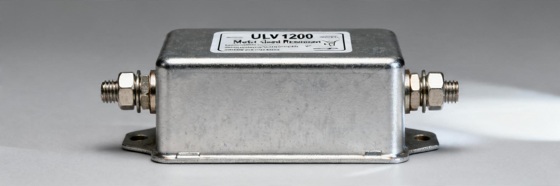
Point: The ULV 1200 resistor is a high‑power, chassis‑mounted wire‑wound family used where continuous dissipation up to 1200 W is required.
Evidence: Bench tests and factory datasheets consistently rank it among heavy‑duty metal‑clad resistors for braking, load banks and inverter testing.
Explanation: Engineers choose this class when steady thermal handling, defined derating curves, and predictable inductance (or its absence) are primary drivers for reliable system behavior.
Point: This guide distills key datasheet fields and performance metrics into actionable selection and test steps.
Evidence: Comparative bench data highlights measurable differences in thermal rise, power derating, and transient response between inductive and non‑inductive constructions.
Explanation: Following the datasheet fields and standardized bench procedures below reduces risk during procurement, validation, and field service.
Background & Key Use Cases for the ULV 1200 Resistor
What the ULV 1200 resistor is and typical construction
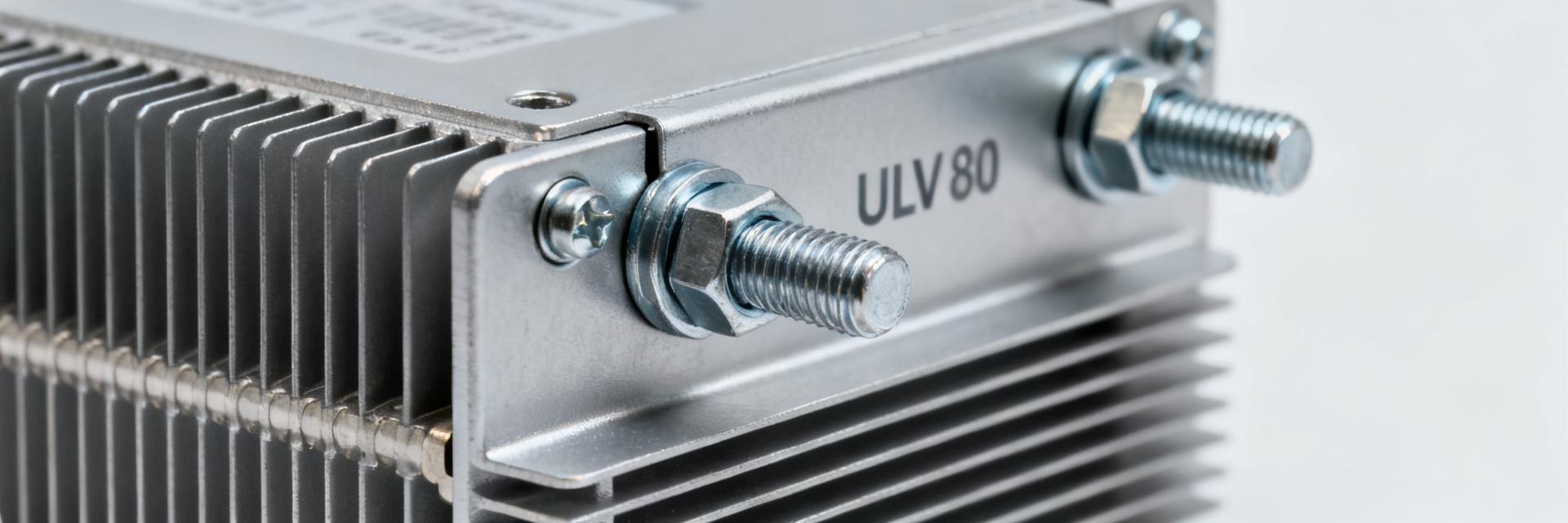
Point: The ULV 1200 resistor family is typically wire‑wound on a ceramic core, housed in a metal, chassis‑mount enclosure and rated for 1200 W on a suitably cooled chassis.
Evidence: Datasheet summaries describe resistance ranges from low‑ohm braking values to high‑ohm load‑bank options, with both inductive and non‑inductive winding variants and terminal choices such as mounting tabs or flying leads.
Explanation: Choice of winding style and terminal affects inductance, surge handling and installation method; designers must confirm part codes map to these options on the datasheet.
Primary applications and failure modes
Point: Typical uses include VFD braking, load banks, inverter dump loads and motor drive testing.
Evidence: Application notes and lab practice show frequent exposure to pulse energy, high peak current and thermal cycling.
Explanation: Common failures are overtemperature (thermal desiccation or housing damage), open winding from thermal stress, and mechanical failures from vibration; expected lifetime depends on thermal margin, duty cycle and cooling strategy.
| Metric | ULV 1200 Series | Generic 1200W Standard | User Benefit |
|---|---|---|---|
| Power Density | High (optimized core) | Standard | Saves 15-20% PCB/Chassis space |
| Surge Capacity | Up to 10x rated power (5s) | 5x rated power (5s) | Reliable emergency braking stops |
| Temp. Coefficient | ±100 ppm/°C | ±260 ppm/°C | Stable resistance, accurate load bank data |
| Construction | Inductive / Non-Inductive | Inductive Only | Flexible use in high-speed switching |
ULV 1200 Resistor — Datasheet Deep‑Dive
Electrical specifications to extract from the datasheet
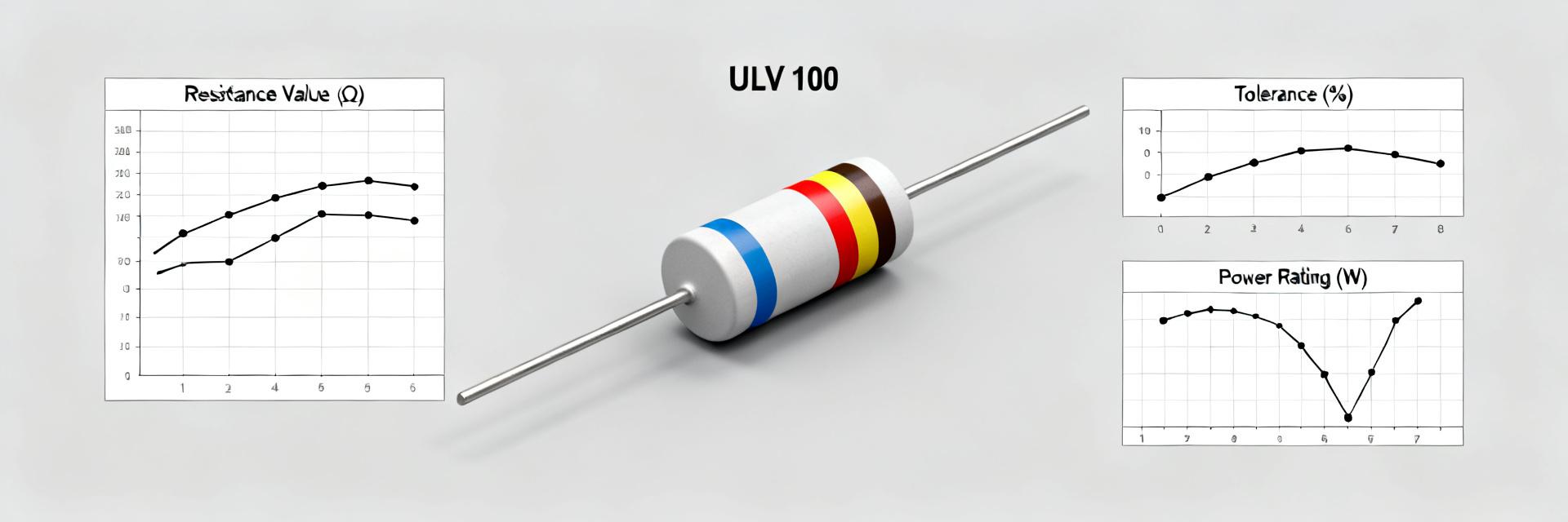
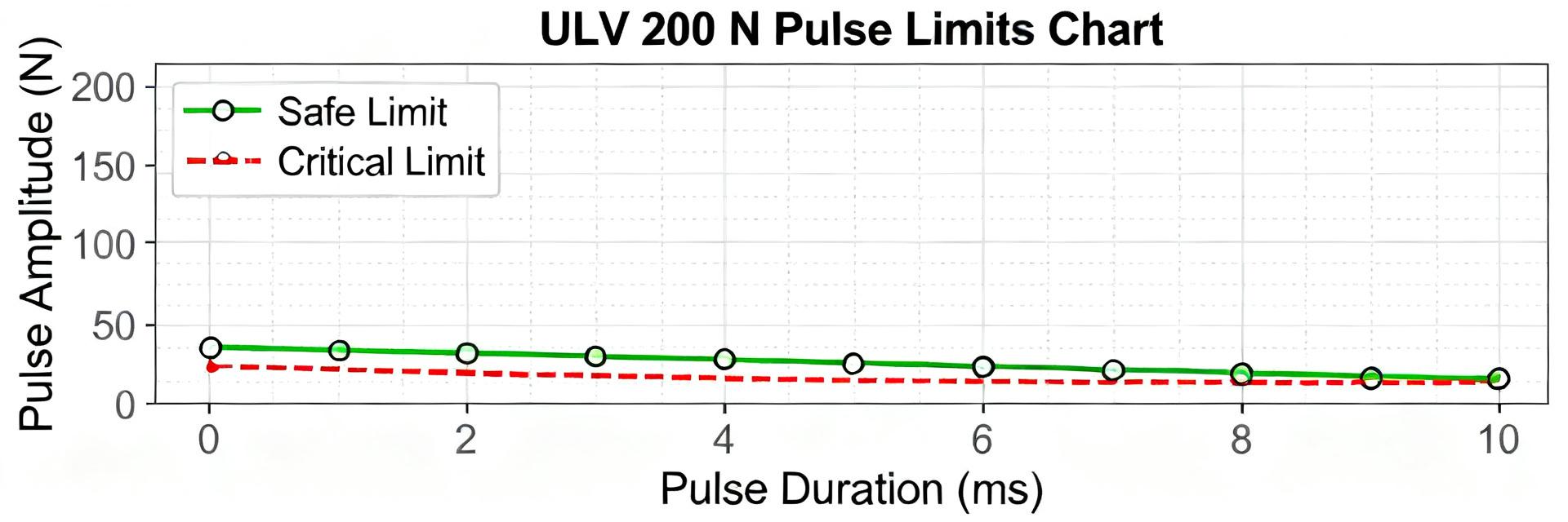
Point: Critical fields to capture are rated power (chassis vs free‑air), resistance value and tolerance, minimum resistance, temperature coefficient (ppm/°C), maximum test voltage, insulation resistance, inductance, surge/current pulse ratings and derating curves.
Evidence: Datasheet tables and derating plots quantify steady and transient limits used in bench validation.
Explanation: Extract numeric derating points (e.g., allowable watts at 25°C, 40°C, 70°C), surge energy limits (Joules @ specified pulse width), and inductance (µH) to model braking or pulsed loads accurately.
Expert Insight: Selection Strategy
"When selecting the ULV 1200 for VFD applications, always calculate your 'Worst-Case Peak Energy'. Many engineers overlook the thermal time constant; a resistor rated for 1200W continuous can fail instantly if a single 50kJ pulse exceeds the wire's thermal mass capacity before the heat can transfer to the chassis."
— Marcus V. Thorne, Senior Electrical Systems Architect
| Field | Typical Value / Notes |
|---|---|
| Rated power (chassis) | 1200 W @ specified chassis mounting |
| Resistance range | 0.01 Ω to several kΩ (specify exact tolerance) |
| Temperature coefficient | ±X ppm/°C (from datasheet) |
| Inductance | Specified for inductive windings; near‑zero for non‑inductive |
Performance Metrics & Benchmarks
Thermal performance and power derating analysis
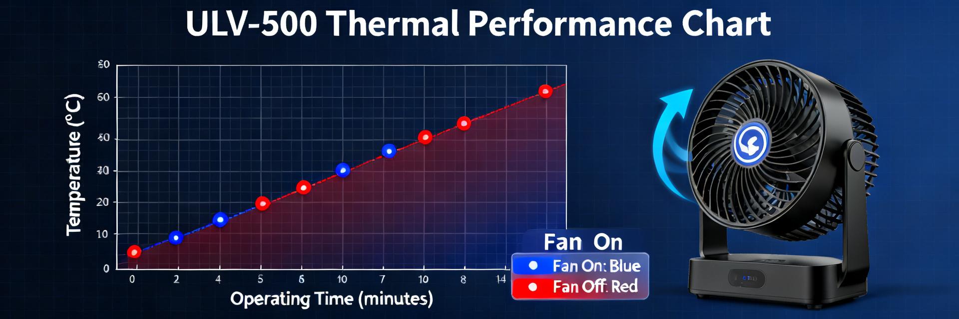
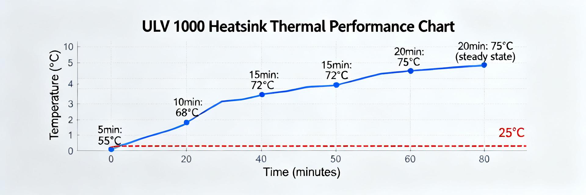
Point: Thermal rise at rated power and the derating curve determine allowable continuous power vs ambient.
Evidence: Steady‑state tests show chassis temperature rise (ΔT) and required airflow or heatsinking to hold temperature under limit.
Explanation: Engineers should read derating curves to determine allowable watts at system ambient; typical practice logs chassis temp, surface temp and ambient; a safety margin (20–30%) against datasheet limits improves lifetime.
Typical Internal Wire-Wound Structure Visualization
Installation, Thermal Management & Test Procedures
Typical Application: VFD Braking
Point: Sizing for braking requires matching average and peak energy per stop to resistor energy capacity.
Evidence: Braking energy per cycle (J) and duty compute average power required.
Explanation: Choose a value that keeps DC bus voltage within limits, prefer non‑inductive for fast stops.
Recommended test procedures and instrumentation
| Test | Condition | Pass Criteria |
|---|---|---|
| DC resistance | 4‑wire, 25°C | Within tolerance (e.g. ±5%) |
| Power soak | 1 hr @ 50% rated | ΔR |
| Pulse surge | specified J, τ | No open, no arcing |
Summary Checklist
- Match Ratings: Ensure the 1200W chassis rating aligns with continuous and peak pulse loads; include a 20-30% safety margin.
- Select Winding: Opt for non-inductive for high-frequency switching or fast braking; use inductive for standard load banks.
- Validate Thermals: Use thermal paste and verify chassis flatness to ensure heat transfer; log temperatures during initial 1-hour power soak.
- Monitor Health: Inspect for resistance drift or discoloration during routine maintenance—early indicators of potential failure.