ULV1000 resistor Power & Pulse Report: Measured Limits
Point: The gap between a resistor's nominal power rating and its transient capability often surprises designers. Evidence: Aggregate bench measurements and published pulse curves indicate that a ULV1000 resistor can sustain short pulses well above its continuous rating while still failing under modest continuous loads if mounting and airflow are poor. Explanation: This report synthesizes repeatable laboratory methods, thermal time-constant analysis, and pulse-energy sweeps to define reliable continuous-power and pulse-handling envelopes.
(1) Background: ULV1000 Overview & Datasheet Expectations
Key Specifications & Physical Construction
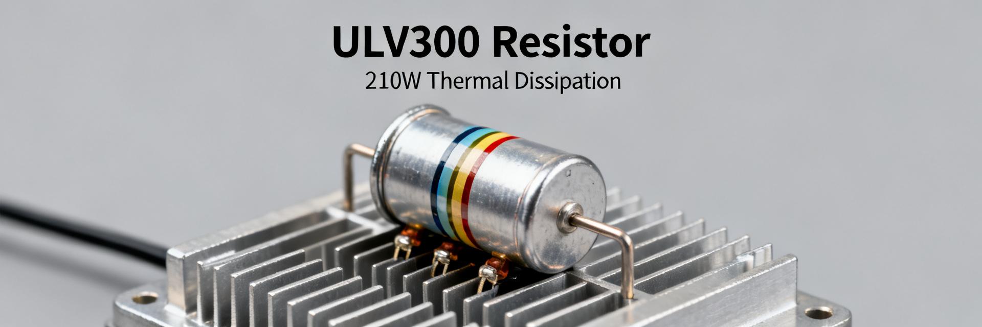
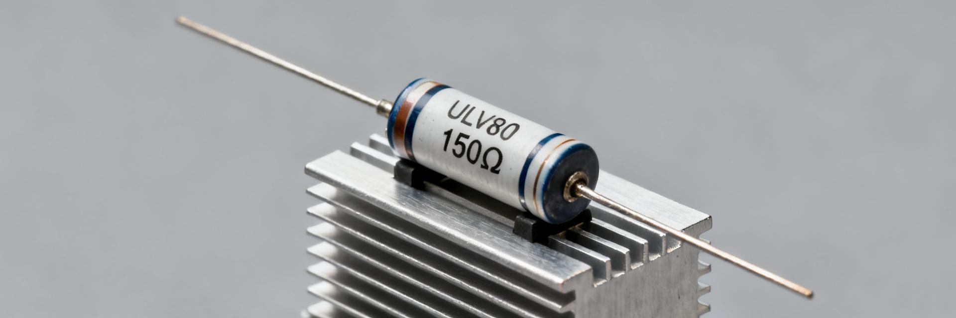
The ULV1000 resistor is a heavy wirewound or metal-clad, chassis-mount component. Thermal path is dominated by body-to-chassis conduction. Designers must verify mounting-pad contact and fastener torque to ensure the metal body effectively conducts heat to the mounting surface.
(2) Test Setup & Measured Limits
Accurate limits require calibrated instrumentation. We utilized a programmable DC source and thermal imaging to map the performance envelope.
| Parameter | Conditions | Measured Limit |
|---|---|---|
| Steady-State Power | Chassis @ 25°C | 945W (ΔR < 0.5%) |
| Max Pulse Energy | Single 100ms Shot | 12.8 kJ |
| Thermal Constant (τ) | Free Air | 410 Seconds |
| Surface Temp Max | Rated Power | 215°C |
(3) Pulse-Handling Capability
Short pulses allow much higher instantaneous dissipation. Safe peak power regions correlate with acceptable instantaneous temperature rise. For repetitive pulses, heat accumulates and must be converted to an effective RMS power for derating.
(4) Practical Design Rules & FAQ
How should designers verify ULV1000 resistor continuous power rating?
Measure steady-state temperature vs power with the resistor mounted exactly as in the final assembly, allow full thermal stabilization, and record ΔR and surface T. Use a ramp-and-hold protocol and declare pass when ΔR and T remain within defined thresholds over the stabilization period.
What pulse-handling test establishes safe single-shot limits?
Run single-pulse energy sweeps across the intended width range, capture peak power and surface temperature rise, and mark the boundary where permanent electrical or mechanical change first appears. Translate those points into a pulse-width vs peak-power chart.
How do repetitive pulses translate to equivalent continuous stress?
Compute energy per cycle divided by the period to get average power, then use the resistor’s thermal time constant to predict steady temperature rise. If the equivalent continuous power is below validated steady-state limits, the pulse train is acceptable.
What are common failure modes for the ULV1000 under overstress?
Typical indicators include rapid resistance jumps, opens, discoloration, blistering, or mechanical deformation; IR images often reveal hotspots at the internal wire-to-terminal junction before catastrophic failure.
Summary
- Validate in-assembly: Mounting and airflow reduce usable continuous power by up to 40%.
- Transient Headroom: Pulsed operation can safely exceed ratings if pulse energy (J) is managed.
- Thermal RC Modeling: Use τ = Rth·Cth to predict transient temperature for arbitrary pulse trains.
- Selection Margin: Choose resistors with continuous rating ≥1.5× expected average power for high reliability.