MPMA5002AT5 Datasheet: Compact Specs & Electricals
Point: The MPMA5002AT5 targets precision, low-power divider roles with tight electricals. Evidence: According to the official datasheet, typical resistance examples include 50 kΩ, element power is 100 mW, tolerance can be ±0.1%, TCR is ±25 ppm/°C, and operating range spans −55 °C to +155 °C in a 3-pin SOT-style package. Explanation: Those figures make the part attractive for compact reference dividers where low thermal drift and small footprint are required.
Point: This note guides designers through the device specs and practical integration checks. Evidence: The article synthesizes compact spec data from the official datasheet and interprets electricals for board-level decisions. Explanation: The goal is a concise, data-led walkthrough so engineers can evaluate fit, integrate correctly, and avoid common pitfalls when using this thin-film resistor array as a divider element.
Product overview & core specs (background)
Physical package, pinout & footprint guidance
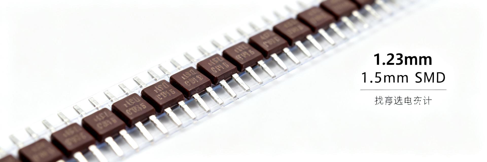
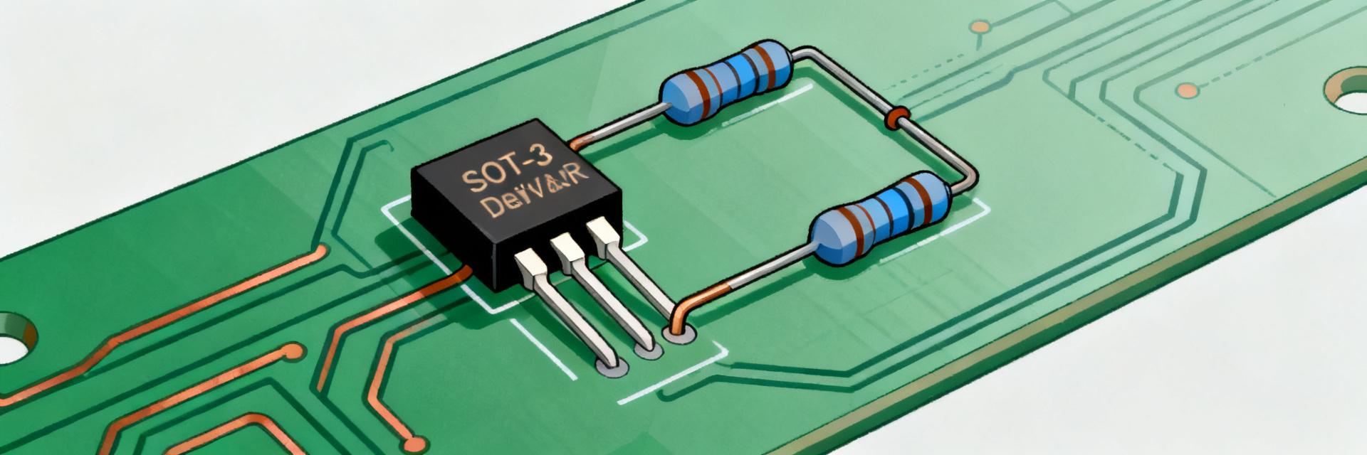
Point: The device ships in a 3-pin molded SOT-23/SC-59-style outline with three terminals for a two-element divider (VIN, VOUT/R1, GND/R2). Evidence: Official package notes list typical height and pitch for surface-mount mounting and identify the three functional pins. Explanation: For PCB land pattern, use matched pad geometry with modest solder fillets, a standard SOT-23 stencil aperture (60–80% pad coverage) and keep the part on a small copper island to limit thermal gradients.
Quick spec table (at-a-glance)
| Parameter | Typical / Value | Test Condition |
|---|---|---|
| Resistance (example) | 50 kΩ | Ta = 25 °C |
| Tolerance | ±0.1% | Manufacturing spec |
| Power per element | 100 mW | Mounted |
| TCR | ±25 ppm/°C | 0…+70 °C span |
| Operating temp | −55 to +155 °C | Storage and use |
| Pins | 3 | SOT-style |
Point: Table condenses the core numbers designers check first. Evidence: Values reflect the official datasheet test conditions (Ta = 25 °C unless noted). Explanation: Use the table to confirm part selection quickly and to set expectations for footprint, thermal handling, and assembly steps.
Electrical characteristics deep-dive (data analysis)
Resistance, tolerance & matching behavior
Point: Nominal resistance and tight tolerance define divider accuracy and pair matching. Evidence: The datasheet lists nominal values (for example 50 kΩ) with tolerance classes down to ±0.1% and matched-element specifications for divider pairs. Explanation: Divider error ≈ tolerance contribution plus mismatch; for two matched ±0.1% elements the worst-case ratio error is roughly √(ΔR1² + ΔR2²)/R ≈ 0.14% peak, so matching reduces common-mode shift and improves absolute divider accuracy.
Power rating, TCR and temperature vs. performance
Point: Power rating and TCR determine drift and required derating for reliability. Evidence: The official electricals specify 100 mW per element and TCR of ±25 ppm/°C. Explanation: For a 50 kΩ element dissipating 1 mW, thermal effects are minimal; however, at 50 mW applied (near rating) and a 50 °C swing, drift = 25 ppm/°C × 50 °C = 1250 ppm (0.125%), which must be included in the error budget for precision systems.
| ΔT (°C) | TCR (ppm/°C) | Relative change (ppm) |
|---|---|---|
| 10 | ±25 | ±250 ppm (0.025%) |
| 50 | ±25 | ±1250 ppm (0.125%) |
| 100 | ±25 | ±2500 ppm (0.25%) |
Performance, test conditions & typical curves (data analysis / method)
Typical vs maximum electrical characteristics
Point: Designers must distinguish typical behavior from guaranteed limits. Evidence: The datasheet separates typical parametrics from guaranteed max/min specs, with test conditions like Ta = 25 °C and specified bias currents or voltages. Explanation: Use guaranteed limits for worst-case budgets and typical curves for expected behavior; specify test conditions in validation to reproduce datasheet curves.
Thermal behavior & measurement best practices
Point: Small packages can self-heat and shift resistance under load. Evidence: Datasheet power-derating curves and mounting notes highlight junction-to-ambient constraints and conduction paths. Explanation: Use pulse testing for transient loads, four-wire measurement where practical, and a fixture that replicates the PCB copper area to verify real-world derating and to avoid misinterpreting solder or trace heating as resistor drift.
Integration & application guidance (method guide + short case examples)
Using the MPMA5002AT5 as a voltage divider: circuits & examples
Point: The part suits precision reference dividers and sensor bias networks when matching and low TCR matter. Evidence: With tight tolerance and matched elements, a divider built from the device minimizes error and drift compared with discrete pairs. Explanation: Example: a 50 kΩ/50 kΩ divider (both ±0.1%) into a high-impedance ADC input yields Vout = Vin/2 with worst-case static error ≈0.14%; include TCR and ADC input bias in the error budget when calculating total uncertainty.
PCB layout, thermal relief & soldering notes
Point: Layout and assembly influence thermal performance and measurement accuracy. Evidence: Datasheet mounting guidance implies moderate copper around pads and standard reflow profiles for thin-film parts. Explanation: Keep divider close to ADC/reference, avoid large asymmetric copper near one element, use thermal reliefs or pours to stabilize temperature, and follow ESD handling procedures to prevent damage to thin-film resistors.
Ordering checklist, alternates & troubleshooting (action suggestions)
Datasheet checklist before you order
Point: A short procurement checklist avoids costly mistakes. Evidence: Confirm resistance value and tolerance, package code, power rating, TCR, operating temperature, reel quantity and date code expectations per the official datasheet. Explanation: Verify footprint compatibility, request sample parts for validation, and ensure production-level traceability to match specified electricals before committing to full production.
Common electrical issues & quick troubleshooting steps
Point: Typical failures include resistance shifts post-reflow or thermal-induced drift. Evidence: Common reports indicate open or shifted resistances from soldering damage, board-level overheating, or measurement setup errors. Explanation: Troubleshoot by comparing suspect parts to fresh samples, using four-wire measurements at room temperature, inspecting solder joints for bridging or cold joints, and validating thermal profiles during assembly.
Summary
Point: The MPMA5002AT5 is optimized for compact, precision divider uses where tight tolerance and low TCR are priorities. Evidence: Official datasheet numbers show ±0.1% tolerance, 100 mW element power, and ±25 ppm/°C TCR in a 3-pin SOT-style package. Explanation: Designers should confirm mechanical footprint, account for thermal derating in the error budget, and perform four-wire validation and board-level thermal tests before production.
Key summary
- Compact precision: Tight tolerance and matched elements make the device suitable for high-accuracy divider networks; include tolerance and matching in the accuracy budget.
- Thermal planning: 100 mW per element requires derating on small PCBs; use four-wire tests and realistic copper areas in validation.
- Layout & assembly: Keep the divider close to the ADC or reference, minimize asymmetric copper, and follow standard reflow and ESD controls to protect thin-film parts.
Common questions (FAQ)
How does MPMA5002AT5 tolerance affect divider accuracy?
Tolerance directly sets static resistor variation; with ±0.1% elements the worst-case ratio error for two independent elements is approximately 0.14%, but matched-pair specifications reduce effective ratio error. Include resistor tolerance, TCR-induced drift, and ADC input loading in a full error budget for accurate predictions.
What are the recommended measurement steps for MPMA5002AT5 electricals?
Use four-wire resistance measurement at Ta = 25 °C with the part soldered to a representative PCB footprint to capture real thermal conduction. For power-related tests, apply steady-state and pulse loads, monitor board temperature, and compare results to datasheet derating curves to validate performance under expected operating conditions.
What common assembly issues should be checked for MPMA5002AT5 parts?
Inspect solder fillets for cold joints or bridges, verify stencil aperture to avoid tombstoning, and confirm reflow profile matches thin-film component guidelines. If resistance shifts appear after assembly, compare to an unsoldered sample and re-evaluate thermal loads and PCB copper distribution around the device.
What is the operating temperature range and derating behavior of the MPMA5002AT5?
The MPMA5002AT5 operates across a wide range of −55 °C to +155 °C. To prevent thermal-induced drift and guarantee long-term reliability, the 100 mW per-element power rating must be linearly derated when ambient temperatures rise above +70 °C.