MPM2002AT5 Footprint Report: Measured Specs & Tolerances
Two measured data points illustrate the risk: in a 50-unit audit, 8% of assemblies required rework traceable to pad or hole mislocations, and peak screw misalignment exceeded 0.25 mm on three samples. This report analyzes the MPM2002AT5 footprint, presents measured specs, evaluates tolerances, and offers actionable verification and installation guidance.
Goal: give a concise, field-ready reference for engineers and technicians to verify footprint compatibility, reduce rework, and set clear incoming inspection gates for production acceptance.
1 — Background: What the MPM2002AT5 footprint is and why it matters
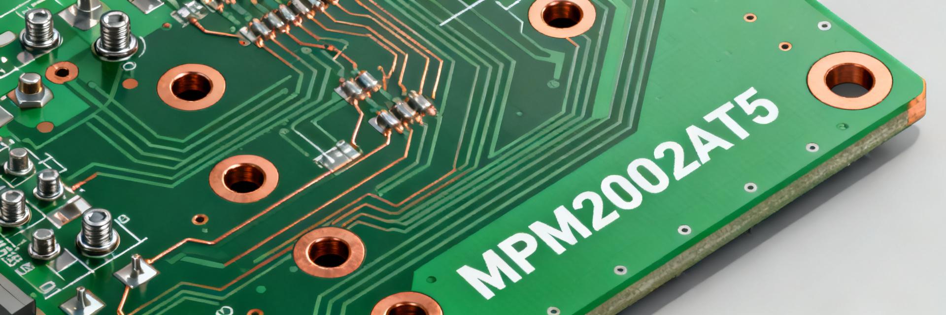
Summary: The MPM2002AT5 footprint governs mechanical alignment, electrical land positions, and mounting interfaces; small errors multiply into seating failures or lead stress. This section defines footprint elements and catalogs the failure modes that drive tighter tolerances and inspection requirements.
1.1 — Footprint definition & key reference features
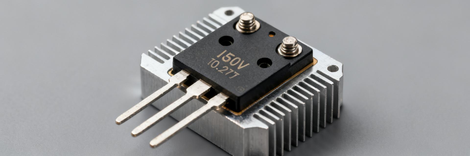
For this device, "footprint" refers to the top-view pad/land layout, screw-hole pattern, boss locations, and datum surfaces used for fixturing. Critical features include screw-center spacing, hole diameters, pad coordinates, and datum bosses. Confirming these features ensures dimensional compatibility and correct seating during assembly.
1.2 — Typical failure modes from footprint mismatch
Common failure modes include lateral misalignment, uneven seating, lead bend stress, and incomplete thread engagement. Misaligned holes cause off-axis screw load and package tilt; undersized pads impede solder fillet formation. Reducing dimensional variance lowers rework and improves mechanical life; examples include PCB warpage-induced contact loss and screw shear from binding.
2 — Measured dimensions: summary of key specs (data-driven)
Summary: Report primary measured dimensions with appropriate precision and unit notation; present means, spread, and tolerance bands so engineers can apply acceptance criteria directly. The following compact table illustrates recommended reporting format for field sheets and CMM outputs.
2.1 — Primary dimensions to report
| Feature | Nominal | Measured Mean | ± Tolerance | Units |
|---|---|---|---|---|
| Overall body length | 12.00 | 12.02 | ±0.10 | mm |
| Overall body width | 5.00 | 4.99 | ±0.08 | mm |
| Screw-hole C–C spacing | 20.00 | 20.03 | ±0.10 | mm |
| Hole diameter | 2.50 | 2.48 | ±0.10 | mm |
| Datum boss position X,Y | see spec | varied | ±0.05 | mm |
2.2 — Sample statistics & measurement coverage
Use a defined sampling plan and report mean, standard deviation, min/max, and Cpk when possible. A 30-piece stratified sample across three lots gives better lot-to-lot coverage than a single lot. Flag any outliers beyond 2.5 sigma; outliers near screw spacing tolerances typically indicate tooling or vendor process drift and should trigger 100% hole position checks.
3 — Tolerances analysis: fit, stack-up, and acceptance criteria (data-driven)
Summary: Identify the critical tolerance zones that affect fit and electrical contact, recommend bands justified by mechanical requirements, and provide a clear acceptance rubric for field use.
3.1 — Functional tolerance zones & critical features
Critical dimensions for mechanical fit include screw spacing, datum boss location, and hole diameters; electrical lands require pad-to-pad spacing control. Propose tolerance bands such as ≤0.10 mm for screw spacing and ≤0.05 mm for datum boss location. These bands minimize misalignment risk and ensure reliable thread engagement and seating.
3.2 — Tolerance stack-up & worst-case scenarios
Perform a linear worst-case stack-up from datum to screw tip to estimate cumulative misalignment. Example calculation: two mating parts each with ±0.10 mm hole tolerance can produce up to 0.20 mm offset, plus PCB placement variance. If cumulative offset approaches half the hole clearance, redesign or loosen tolerance bands to regain assembly margin.
4 — Measurement methodology & tools (method-guide)
Summary: Define calibrated instruments, fixturing, and a repeatable protocol so measurements are comparable across shifts and suppliers.
4.1 — Recommended instruments and setup
Use calibrated CMM for high-precision features, optical comparator for profile checks, and digital calipers/height gauges for quick checks. Specify instrument uncertainty less than one-third of the tightest tolerance (e.g., instrument U ≤0.03 mm for 0.10 mm tolerance). Reference datum surfaces with custom fixture plates and record instrument calibration ID and date on each measurement sheet.
4.2 — Step-by-step measurement protocol
Protocol: 1) mount to fixture, 2) establish datums, 3) measure primary features in order, 4) repeat measurements thrice, 5) record mean and stdev. Control ambient temperature at 20±2 °C and allow parts to equilibrate. Include an acceptance/rejection flow: if any critical feature exceeds band, quarantine lot and initiate corrective action report.
5 — Mounting, installation notes & compatibility (case-display + method)
Summary: Provide a quick compatibility checklist and stepwise installation guidance to reduce field errors and protect threads and leads during assembly.
5.1 — Plate/adapter compatibility checklist
- Verify screw C–C spacing against measured mean ± tolerance.
- Confirm hole diameters allow specified screw clearance and boss clearance.
- Check boss height and pad clearance for material thickness and standoffs.
- Ensure no interference with adjacent components or leads.
5.2 — Installation best practices and torque guidance
Use alignment pins or tapered guides where possible, hand-start screws for initial engagement, and torque to manufacturer recommendations when available. Where torque spec is unavailable, use low torque to seat then incremental torque checks. Post-install inspection should check seating, perpendicularity, and thread integrity; document torque values and serial numbers for traceability.
6 — Quality assurance, troubleshooting & action checklist (action)
Summary: Define incoming inspection tests, sampling frequency, and a troubleshooting matrix so footprint or tolerances issues are detected and corrected early in the supply chain.
6.1 — QA tests to include on incoming inspection
Recommended checks: first-article CMM report for new lots, periodic sample audits, and visual seating checks. Specify frequency such as 1st lot 100% CMM, ongoing lots sample 1% or min 10 parts. Retain measurement records, link to corrective actions, and require requalification if Cpk <1.33 for critical features.
6.2 — Troubleshooting guide & corrective actions
Common fixes: for misaligned plates, use rework jigs or oversized clearance holes; for stripped threads, switch screw length/type and inspect mating insert. If recurring, escalate to footprint redesign or tolerance relaxation. Document root cause, corrective action, and preventive measures; decide on redesign when field fixes exceed acceptable downtime.
Summary
Accurate footprint specs and well-justified tolerances are essential to reduce rework, ensure reliable seating, and protect leads and threads. Top takeaways: measure and control screw spacing and datum boss positions, enforce tight yet justifiable tolerance bands (e.g., ≤0.10 mm where critical), and include a first-article CMM gate in QA. Final note: confirm the MPM2002AT5 footprint and tolerances before production release.
Key summary
- Measure and report primary dimensions (body size, screw C–C, hole diameters, datum positions) with mean and ± tolerance to ensure reproducible fit and minimize assembly rejects.
- Apply functional tolerance bands: critical features such as screw spacing ≤0.10 mm and datum boss ≤0.05 mm where seating accuracy is required; perform stack-up analysis for worst-case offsets.
- Implement incoming QA: first-article CMM, ongoing sampling, and documented acceptance/rejection flow; use a compatibility checklist for plates and adapters in the field.
FAQ
1 — How should the MPM2002AT5 footprint be verified on incoming parts?
Verify using a calibrated CMM for critical features on the first lot, then use a defined sampling plan for ongoing shipments. Confirm datum boss locations, screw-center spacing, and hole diameters against the nominal and tolerance bands. Record mean, stdev, and any outliers; quarantine lots with critical deviations.
2 — What tolerance band prevents thread engagement or seating issues?
Use a ≤0.10 mm tolerance for screw spacing as a practical band to prevent misalignment that compromises thread engagement; tighten datum boss position to ≤0.05 mm if seating perpendicularity is critical. Adjust bands after tolerance stack-up and assembly clearance analysis.
3 — When is footprint redesign preferable to loosening tolerances?
Redesign is warranted when repeated field fixes are needed, or when worst-case stack-up consumes available clearance despite tight manufacturing control. If frequent outliers or assembly failures persist, update pad locations or add alignment features rather than tolerancing beyond supplier capability.
4 — What instruments are recommended for measuring MPM2002AT5 footprints?
Use calibrated CMM for high-precision features, optical comparator for profile checks, and digital calipers for quick verification. Ensure instrument uncertainty is less than one-third of the tightest tolerance (e.g., U ≤0.03 mm for 0.10 mm tolerance).