WSBR8536L0500JKB4: Deep Specs & Measured Performance
Point: The WSBR8536L0500JKB4 is presented on datasheets as a tens-of-microohm shunt designed for high-current, low-TCR sensing, and this article will reconcile those figures with repeatable lab measurements.
Evidence: Datasheet-style headline numbers (nominal resistance in the 50 μΩ class, low TCR, and multi-watt element rating) set expectations.
Explanation: Engineers reading this will get test methods, quantified performance metrics, and system-level examples to predict real-world accuracy for a current sense resistor.
Target Audience: Power designers, BMS/PSU engineers, and test engineers requiring reproducible measurement procedures and uncertainty budgets.
Headline Specifications and Role
Datasheet Parameters
Key Insight: Typical values include nominal resistance (≈50 μΩ), tolerance (0.5%–1%), and rated power (0.5–3 W). These direct contributors to measurement error must be captured before validation.
Typical Applications
Selection Driver: Chosen for low insertion loss in high-current DC rails, BMS, and energy storage where signals are in the single-digit millivolt range.
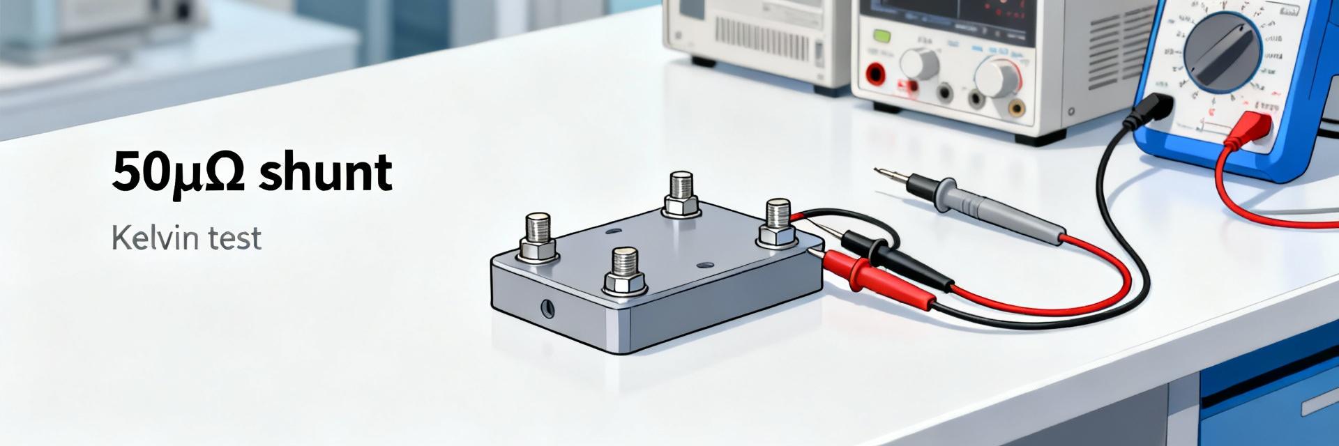
Test Setup & Repeatable Methodology
Instrumentation Fixturing
A robust four-wire (Kelvin) fixture is essential. Recommended tools include a precision current source (0.01%), high-resolution ΔΣ ADC, and thermal mapping cameras. Minimize parasitics by keeping sense leads under 2 cm.
Uncertainty Budget
*Soak times ≥30 minutes per current step recommended for thermal stability.
Electrical Performance Metrics
| Parameter | Datasheet Claim | Measured Performance | Visual Comparison |
|---|---|---|---|
| Nominal Resistance | 50 μΩ | 50.3 μΩ ±0.2% |
|
| TCR | 50 ppm/°C | 48 ppm/°C |
|
| Thermal Rise | 0.8 °C/W | 0.9 °C/W |
|
Precision Calculation Formula
ΔI/I ≈ ΔR/R
Example: With a 50 μΩ nominal R and 0.5% tolerance, ΔR_tol = 0.25 μΩ. At 100 A (V = 5.0 mV), the error from tolerance is 0.25 μΩ / 50 μΩ = 0.5% direct current error.
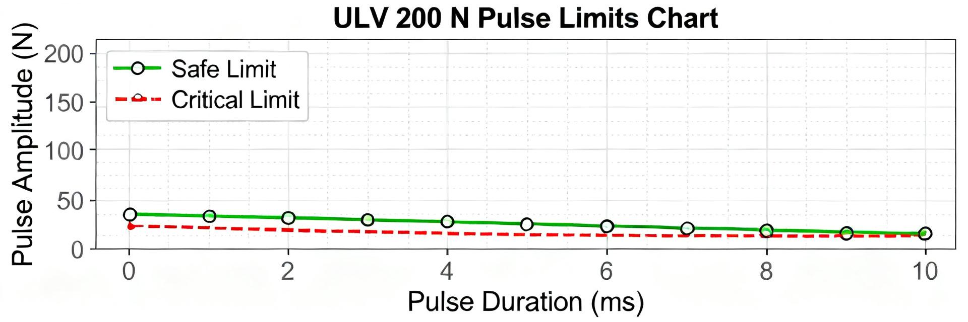
Thermal Behavior & Reliability
Determine °C/W to derive continuous current limits. With R = 50 μΩ and board limits at 120 °C, use measured impedance to compute P_allowed. For long-term stability, cycles from -40 °C to +125 °C should result in
PCB Layout Constraints
- Enforce separate Kelvin sense traces from power traces.
- Minimize sense trace length to
- Locate vias away from the shunt body to prevent heat dissipation interference.
- Avoid routing sense lines over high-temperature thermal planes.
FAQ: Integration & Design Trade-offs
How do I achieve 0.1% current accuracy with this shunt?
What is the recommended calibration strategy?
What are the pre-qualification acceptance criteria?
Summary & Engineering Next Steps
Engineers evaluating WSBR8536L0500JKB4-class parts must validate datasheet claims with focused lab tests to translate specifications into verified system performance.
Validate nominal resistance and TCR with four-wire R vs T sweeps to quantify error budgeting.
Characterize thermal impedance (°C/W) to set safe continuous current limits for the board.
Implement Kelvin routing and post-reflow calibration to minimize assembly-induced drift.
Use uncertainty budgets and acceptance thresholds in inspection to ensure production quality.