MPM5002AT5 Datasheet Deep Dive: Specs & Tolerance Guide
Small tolerance shifts matter: in a 25 kΩ divider, a worst-case ±0.1%/±0.1% resistor pair mismatch produces ≈0.05% output error—enough to shift a 16-bit ADC reading by multiple LSBs. This article decodes the MPM5002AT5 datasheet to extract the specs designers must verify, show how tolerance and matching affect precision circuits, and provide practical verification and selection guidance for reliable results.
The goal is practical: identify the datasheet numbers that control accuracy, explain measurement conditions and units, and give bench and layout recipes that let engineers validate tolerance, matching, TCR, and long-term behavior in production and prototype phases.
Background & Part Overview
What the MPM5002AT5 is and typical applications
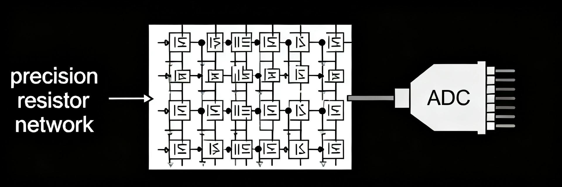
The MPM5002AT5 is a precision resistor network / divider optimized for ADC front ends, sensor dividers, and gain/reference networks. Its core specs—nominal resistance, tolerance, and element-to-element matching—drive accuracy in low-noise measurement chains. Designers check these specs to decide whether firmware trimming or hardware selection is required for target system error budgets.
How to read the datasheet header and part code
Datasheet headers show part numbering, package code, and ordering options; locate the electrical specs table, absolute maximum ratings, and mechanical drawings immediately after the header. Quick checks: confirm nominal resistance, tolerance class, and package thermal notes before deep reading—these items determine test conditions and expected behavior across temperature and power.
MPM5002AT5 datasheet — Electrical Specs Deep Dive
Resistor values, tolerance, matching ratio, and power ratings
The electrical table lists nominal resistance (for example, 25 kΩ), stated initial tolerance, and specified matching or ratio between elements. Tolerance is typically given as ±% under a defined test temperature; matching is expressed as a ratio or ΔR and often tighter than absolute tolerance. Per-element power rating and test conditions (ambient temperature, test current) indicate how power affects resistance and error.
Package, pinout, and thermal/electrical limits
Mechanical drawings specify package dimensions and pin assignments; thermal resistance (θJA) and max operating temperature appear in limits. Absolute maximums list supply or voltage stress and thermal derating notes. Designers must translate θJA and board copper to expected junction rise and verify that layout and footprint notes match the recommended land pattern to avoid thermal or soldering issues.
MPM5002AT5 datasheet — Tolerance, Matching & Circuit Impact
What tolerance and matching specs actually mean
Tolerance is the allowable initial deviation from nominal resistance; matching specifies the relative error between elements in a network. Datasheets state test methods—sample sizes, measurement temperature, and whether matching is guaranteed across the full tolerance band. Designers use matching for ratio-critical circuits where relative error matters more than absolute value.
Quantifying circuit error: worked examples
Illustrative calculation: a 25 kΩ divider with ±0.1% resistors yields roughly ±0.05% Vout error when pair mismatch is the dominating term. In contrast, a matched network rated for ±0.02% matching reduces divider error by several×, improving ADC LSB stability. Worst-case tolerance drift can dominate if TCR or aging shifts occur; matched networks limit differential error.
Reliability, Temperature Coefficient & Aging (Data Analysis)
Temperature coefficient (TCR) and environmental limits
TCR is given in ppm/°C and converts to percent change per temperature span. For example, 25 ppm/°C over a 50°C swing yields a 0.125% change. Read the datasheet TCR section for per-element and differential TCR values—differential TCR is critical for ratio stability across temperature. Environmental limits list operating and storage ranges that bound practical use.
Long-term drift, humidity, and derating guidance
Datasheets often specify long-term stability in ppm/year and list humidity or IO testing (e.g., MIL or IEC-style cycles). As a rule of thumb, specify tighter initial tolerance and matching than needed, allow firmware trim for offset, and place networks away from heat sources. For production, derate power relative to per-element ratings to reduce drift and extend stability.
Test & Validation Methods — How to Verify Specs on the Bench
Bench tests to measure resistance, tolerance, and matching
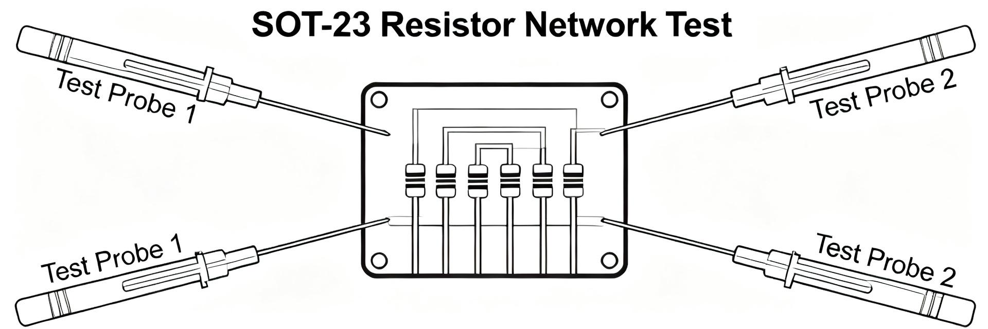
Use four‑wire (Kelvin) measurement or a precision bridge to measure each element at stabilized temperature. Test a representative sample size and record ambient. Compute tolerance as (measured−nominal)/nominal and matching as ΔR between elements divided by nominal. Apply pass/fail thresholds from the datasheet: initial tolerance and stated matching limits.
Thermal and stress testing to verify real-world behavior
Perform thermal-soak tests using a temperature chamber or localized hotplate to measure TCR and ratio drift. Run temperature cycling and humidity soak per the datasheet’s recommended conditions to reveal failure modes. Log results and compare statistical distributions to the datasheet claims; use a small production sampling plan for QA.
Application & Selection Checklist — Choosing and Specifying MPM5002AT5
| Item | Callout |
|---|---|
| Resistance | Nominal value and tolerance |
| Matching | ΔR or ratio spec |
| TCR | ppm/°C, differential TCR |
| Power & Temp | Per-element power, operating range |
Layout and integration tips (practical do’s & don’ts)
Place the network close to the ADC input to minimize trace length and noise; avoid routing high power traces nearby to prevent thermal gradients. Use symmetric routing for differential dividers, solid ground reference, and keep decoupling close to sensitive ICs. Implement one-point or two-point firmware calibration when absolute precision is required.
Summary
Careful reading of the MPM5002AT5 datasheet unlocks correct part selection and reliable performance. Prioritize the resistors’ nominal value, tolerance, element matching, and TCR when budgeting accuracy. Validate on the bench with Kelvin measurements, thermal soak, and a sampling QA plan to confirm datasheet claims and catch assembly or layout issues early.
Key Summary
- Check nominal resistance and the datasheet specs for initial tolerance and matching—matching often controls ratio error more than absolute tolerance.
- Read TCR (ppm/°C) and differential TCR to predict temperature-induced drift across your operating swing; convert ppm to percent for system impact.
- Verify per-element power rating and θJA with your PCB thermal context; derate to reduce long-term drift and improve reliability.
- Use four‑wire measurements and thermal soak tests to validate tolerance, matching, and aging claims before production.
Frequently Asked Questions
How does tolerance on the MPM5002AT5 affect ADC accuracy?
Absolute tolerance shifts the divider offset, introducing a systematic error in ADC reference or signal scale. Relative matching between elements determines differential error. For high-resolution ADCs, even 0.05% divider error can move multiple LSBs, so designers choose matched networks or calibrate in firmware to compensate.
What test methods confirm the datasheet matching spec?
Use precision Kelvin measurements on pairs of elements under controlled temperature. Measure multiple samples, compute ΔR/norm, and compare to the stated matching limit. Thermal soak and cycling help reveal whether matching holds across expected temperature swings.
When should I rely on hardware selection vs. firmware calibration?
If system error budgets require low drift and minimal calibration, select parts with tighter specs (matching and low TCR). If cost or availability constrain component choice, plan a reliable firmware calibration routine (one-point or two-point) and ensure stability practices in layout to minimize calibration shifts.
How does the SOT-23 / TO-236 package of the MPM5002AT5 affect thermal tracking?
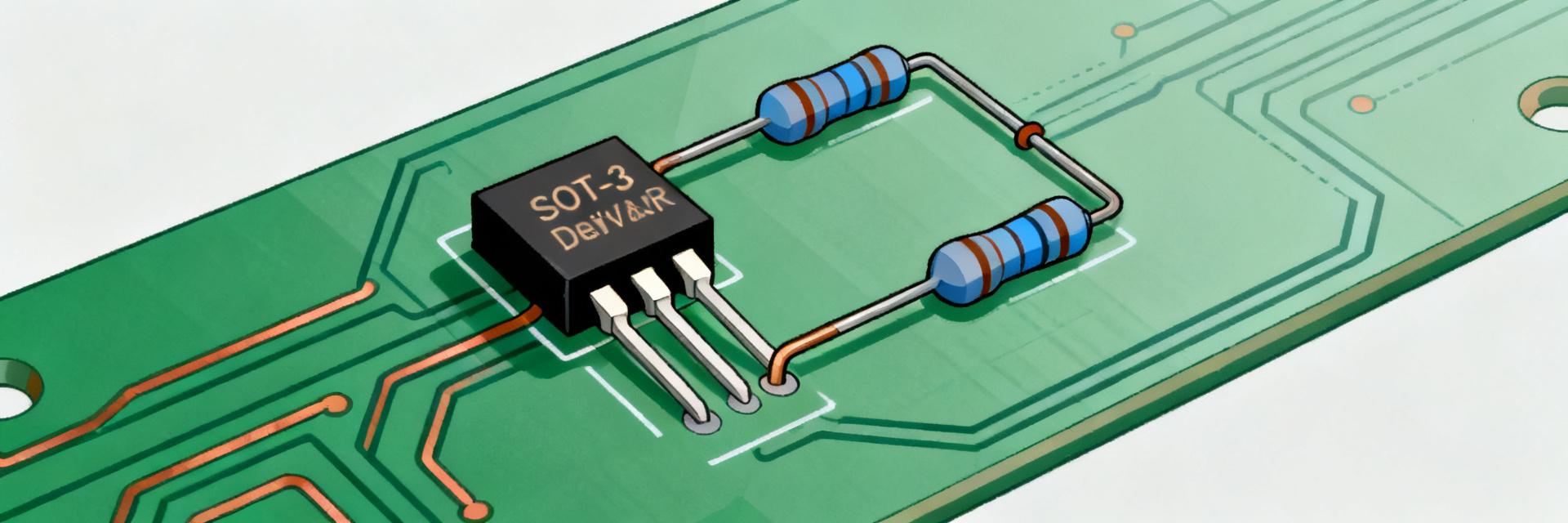
The monolithic integration on a single silicon substrate ensures that both resistors (R1 and R2) share an identical thermal environment. This minimizes localized temperature gradients, allowing the differential TCR tracking to remain within exceptionally tight limits (often < 2 ppm/°C) compared to discrete matched pairs.